I-MICN-01.doc
Issue
06
Mar10
5
IOM –
MICRONEX - ZONE 2
FLOODLIGHT (ATEX, Ex n)
supplies should be sought from
the Technical Department.
3.4
Lamps
The Micronex uses double
ended HPS and MBI lamps and
are of a standardised type, with
no preference between make or
colour. All have RX7 caps.
Care must be taken to fit the
correct new and replacement
lamp in order to preserve the
certification conditions and
obtain the designed
photometric performance.
The
lamp type is shown on the
rating plate
. Lamps should be
replaced shortly after they do
not light.
One indication of the
end of life for HPS lamps is
'cycling', where the lamp goes
out then re-ignites after a
minute or so interval. If
discharge luminaires are
burned continuously, they
should be switched off
occasionally to allow old lamps
to fail to re-ignite, rather than
possibly become diodes with
detrimental effects to control
gear.
The above information is
current at the time of
preparation. The development
of lamps and control gear is
ongoing and detailed advice on
lamp performance can be
obtained from the lamp supplier
or from Chalmit.
Note:
HPS and MBI
circuits should not be energised
without a lamp fitted. HPS and
MBI lamps with
internal
ignitors must not be used.
3.5
Mounting
Luminaires should be installed
where access for maintenance
is practical and in accordance
with any lighting design
information provided for the
installation. The stirrup
mounting arrangements should
be secured with lock washers
or self-locking nuts and bolts.
There are clearance holes for
M10 bolts. The luminaire
should be mounted with the
lamp axis horizontal.
3.5.1 Weights
and
Windages
The weights and windages for
the various floodlight types are
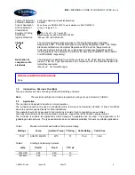
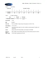
outlined in TABLE 4.
3.6
Cabling and Cable
Glands
3.6.1 Cables
The cable entry temperatures
are given as the rise over the
maximum rated ambient. This
allows the user to adjust the
cable specification for the
actual site maximum
temperature. The terminals are
suitable for standard conductor
section up to 6mm² max. All
models are suitable for looping.
Standard 300/500V cable is
suitable. The cable makeup
must be suitable to ensure the
obtaining of a restricted
breathing enclosure when the
cable gland assembly is fitted.
It is strongly advisable to use a
high quality and well filled cable
with direct entry into restricted
breathing luminaires.
3.6.2 Cable Glands
Cable glands and sealing plugs
when installed must maintain
the restricted breathing
enclosure. Entries suitable for
M20 cable glands are standard.
To maintain the restricted
breathing properties of the
enclosure a suitable cable
gland such as a Hawke
501/453/RAC type should be
installed or a cable gland
satisfying the following
requirements:
The cable gland must
satisfy the requirements for
en 60079-0 and must
maintain an ingress rating
of at least IP65.
The certified cable gland is
to be a compression type
gland where the cable
sheath is evenly
compressed when
tightened or an Ex d
stuffing type or a punched
seal type.
To enable a reliable seal at
the cable entry face a
neoprene or silicone
rubber washer and a
stainless steel washer are
provided for each entry
and must be fitted.
3.7
Cabling and Fitting
Lamps
Access for cabling and fitting
lamps is by removing the front
cover. The cover is released by
undoing the two screws using a
screwdriver. Reselect the
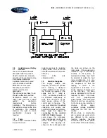
voltage tappings if necessary.
Install the conductors in the
appropriate terminals. Take
care not to cut back the
insulation excessively, 1mm
bare conductor outside the
terminal is a maximum. Any
unused terminal should be fully
tightened.
When the cabling is complete,
make a final tightness and
connection check.
Lamps must be of the correct
type and correctly in place. The
cover is replaced and the
screws tightened down.
3.8
Inspection and
Maintenance
Visual inspection should be
carried out at a minimum of 12
monthly intervals and more
frequently if conditions are
severe. The time between
lamp changes could be very
infrequent and this is too long a
period without inspection.
3.8.1 Routine Examination
(a)
The equipment must be de-
energised before opening.
Individual organisations will
have their own procedures.
What follows are guidelines
based on
BS EN 60079-17
and
on our experience :
1.
Ensure the lamp is lit
when energised and


