background image

1

Before you begin

1

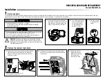
Installation

RECEIVER LOGIC BOARD REPLACEMENT

Model 050ACTWFLK

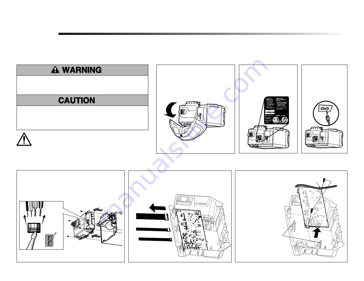
1.1  

Remove the light lens by pulling the 
top sides of the light lens and rotate the 
light lens down. Squeeze the light lens 
clips to remove lens from end panel.

Remove the receiver logic board

2

2.2  

Unplug the wire harnesses from the receiver logic 
board. You may need needle-nosed pliers to remove 
the harnesses.

2.3

   Remove the receiver 

logic board from the 
end panel by removing 
the 2 screws and 
releasing the 2 clips.

Screws

Wire clip

Clips

To prevent possible SERIOUS INJURY or DEATH:
•  Disconnect ALL electric and battery power BEFORE performing ANY

service or maintenance.

WARNING:

 This product can expose you to chemicals including 

lead, which are known to the State of California to cause cancer or 
birth defects or other reproductive harm. For more information go to 

www.P65Warnings.ca.gov

To prevent damage to the receiver/logic board, DO NOT touch printed circuit 
board of replacement receiver/logic board during installation.
ALWAYS wear protective gloves and eye protection when changing the 
battery or working around the battery compartment. 

1.2  

To maintain your warranty, 
place the provided label 
over the existing label 
on the end panel of the 
garage door opener.

Your garage door opener has an internal gateway located on the receiver logic board. After installing the new receiver logic board, use the MyQ

®

 serial number found on the provided label to add your 

garage door opener to your MyQ

®

 account. The products illustrated in the instructions are for reference. Your product may look different.

1.3  

Disconnect power 
to the garage door 
opener.

2.1  

Disconnect the wires from the quick-connect terminals 
(

A

). Disconnect any wires from the lock terminals. 

Remove the receiver logic board end panel from the 
garage door opener. 

A

To insert or remove the wires from the terminal, 
push in the tab with a screwdriver tip.

Lock 

Terminals

Red

White

White

Grey

Summary of Contents for 050ACTWFLK

Page 1: ...s ca gov To prevent damage to the receiver logic board DO NOT touch printed circuit board of replacement receiver logic board during installation ALWAYS wear protective gloves and eye protection when...

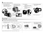
Page 2: ...installing the light lens ensure the antenna wires are hanging straight down To program the Wi Fi garage door opener to your network refer to your owner s manual 3 2 Insert the antenna wires through...

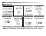
Page 3: ...Button until the door is in the desired DOWN position NOTE The UP and DOWN Buttons can be used to move the door up and down as needed 1 5 Once the door is in the desired DOWN position press and relea...

Page 4: ...or stops and does not reverse on the obstruction increase the down travel refer to Adjustment Step 1 Repeat the test When the door reverses upon contact with the 1 1 2 inch board remove the board and...

Page 5: ...n secteur AVANT TOUTE r paration ou maintenance ATTENTION AVERTISSEMENT AVERTISSEMENT AVERTISSEMENT Votre ouvre porte de garage a un portail interne localise sur la plaque de logique de r ception Apr...

Page 6: ...en l enclenchant en place Reconnectez l alimentation REMARQUE Lors de l installation de la lentille s assurer que les ls d antenne sont orient s vers le sol 3 2 Ins rez les ls d antenne travers les t...

Page 7: ...porte vers le haut et le bas au besoin REMARQUE On peut utiliser les boutons UP et DOWN pour d placer la porte vers le haut et le bas au besoin 1 4 Appuyer sur le bouton DOWN et le maintenir enfonc j...

Page 8: ...e n 1 R p ter l essai Lorsque la porte remonte au contact de la planche de 3 8 cm 1 1 2 po retirer la planche et ouvrir fermer la porte 3 ou 4 fois a n de v ri er le r glage Si l essai choue encore ap...

Page 9: ...tor NO toque la tarjeta de circuito impresa de la tarjeta l gica del receptor de reemplazo durante la instalaci n SIEMPRE uso los guantes protectores y protecci n ocular cuando cambiar la bater a o tr...

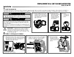
Page 10: ...4 Instale la lente de luz aline ndola con las bisagras y coloc ndola en su lugar Vuelva a conectar la energ a NOTA Al instalar la lente de luz aseg rese de que los cables de la antena cuelguen derecho...

Page 11: ...se encuentre en la posici n deseada 1 5 Una vez que la puerta est en la posici n deseada oprima y suelte el Bot n ajuste Las luces del abre puertas de garaje parpadear n dos veces y el bot n ARRIBA co...

Page 12: ...eba Cuando la puerta retroceda al entrar en contacto con la tabla de 3 8 cm 1 1 2 de pulg retire la tabla y abra cierre la puerta 3 4 veces para probar el ajuste Si la prueba sigue fallando llame a un...

Reviews: