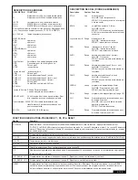
TECHNICAL DATA
Voltage:
230V~ ±10% 50-60Hz
Transformer:
230V/24V, 150VA
Output Motor:
24V/DC
Consumption max.:
max. 400W (in operation)
Consumption Standby:
max. 4 Watt (without accessories)
Supply accessories:
24VDc / 600mA max.
Operating temperature:
-25ºC ÷ 55ºC
Modes:
Standard,
Automatic
Measurements:
250x75mm (without box)
Measurements Box:
ca. 300mm x 220mm x 120mm
Protection class Box:
IP45
Fuse:
2 x 2A fast-blow
Remote control:
max. 170
Feasible frequencies:
433MHz, 868MHz
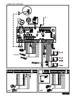
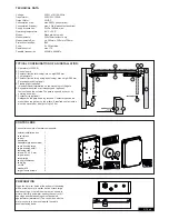
TYPICAL CONFIGURATION OF AN INSTALLATION:
1. Operators (LYN/SCS)
2. Control board
3. Photocell (active for closing), max. height 200 mm
First photocell.
4. Photocell (active for opening and closing), max. height 200 mm
Second photocell (optional).
5. Flashing light (optional)
Important visual information on the movement of the gate.
6. Key-operated switch or wireless keypad (optional)
Is mounted on the outside. The gate is opened by key or by
entering a number.
7. Contact strip (optional)
Safeguards the gate on being touched. Contact strips can be
mounted on the gate or on the pillars. If required, contact strips
must be mounted at a height of up to 2.5m.
2/16 en
CONTROL BOX
The control consists of several components.
- exterior installation box
1
- cover for box
1
- control
1
- transformer
1
- baseplate (pre-assembled) 1
- cable bushing large
1
- cable bushing small
3
- fastening clips
6
- screws 3,5 x 9,5 mm
4
- large washer
1
- screw large
1
- spring lock washer
1
- cable lug
1
- nut M8
2
- washer M8
1
- large closure screws
5
PREPARATION
Open the 4 pre-cut holes at the bottom of the casing
with a screwdriver or a similar device. Attach large
cable bushing on the left then the rest as shown in
picture. Humidity and water destroy the control. All
openings and cable bushings must be sealed
against water (waterproof). The control box with the
motor control is to be mounted with the cable
bushings facing down.
4
+
Summary of Contents for ART300 series
Page 23: ...ART 1 ART 2 ART 3 ART 6 ART 7 115 o 90 o 90 o 90 o 115 o 115 o 115 o 90 o 1 A B 2 3 A...
Page 25: ...6 7 8 9 A B 10 11 A B C D...
Page 26: ...ART 6 ART 7 41ABSC 5 41ASWG 454 41AART 63 ART 3AL 41AART 1022SA 41AART 1026SA 13 12...
Page 27: ......
Page 28: ...709446D 2010...
Page 234: ......
Page 235: ......

