Rev C
Doc 6001287 (01-20284)
9 of 40
CAUTION
The total weight of the gate arm must not exceed ten (10) pounds. The lighter and/or shorter the
gate arm, the longer the life of the gear reducer and motor.
1. ARM ATTACHMENT
1. Secure the hub flange to the output shaft using the two set screws and the key from the
accessory kit.
2. Align the holes in the gate arm with the attachment holes on the hub flange and arm clamp.
3. Install and tighten the four supplied hex bolts, lock washers and hex nuts (see Figure 6).
NOTE:
Make sure the arm clamp is oriented as shown in the figure.
H.
GATE ARM ADJUSTMENT FOR TYPICAL INSTALLATION
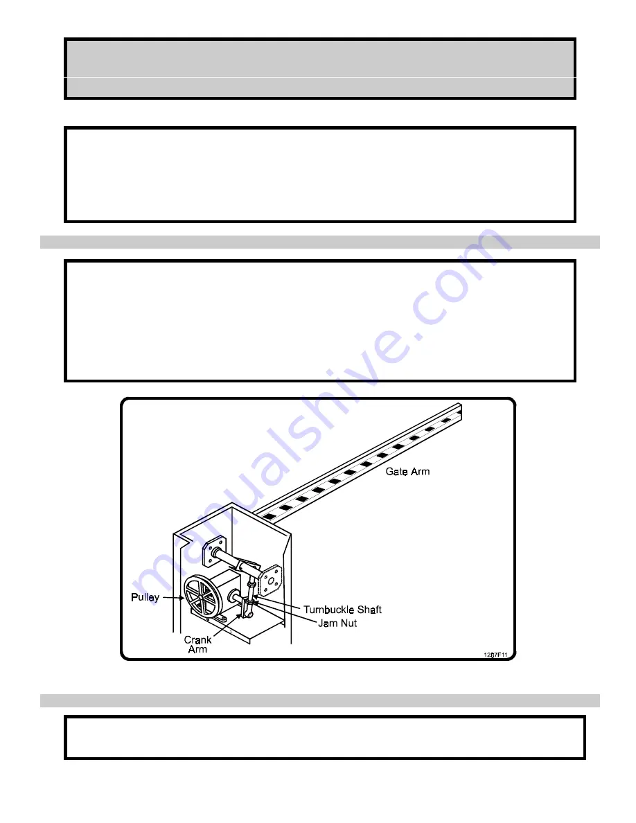
Although preset at the factory, the turnbuckle may have to be adjusted to ensure the gate arm is
level. If required, adjust the turnbuckle as follows:
1. Make sure the unit power switch is off.
2. Rotate the gearbox pulley by hand until the crank arm is in parallel with the turnbuckle shaft
at its lowest point of travel (see Figure 7).
3. If the gate arm is not level, loosen both turnbuckle jam nuts and rotate the shaft until the gate
arm is parallel with the ground, then retighten the two jam nuts.
Figure 7. Gate Arm Adjustment.
I.
LIMIT CAMS
Gate operator limit cams are factory adjusted for 90
0
arm swing and are not to be adjusted in the
field except during limit cam or limit switch bracket replacement.


