background image

51

Summary of Contents for C2102C

Page 1: ...e read this manual and the enclosed safety materials carefully Fasten the manual near the garage door after installation The door WILL NOT CLOSE unless the Protector System is connected and properly a...

Page 2: ...e 43 RepairParts 45 Rail Assembly Parts 45 Installation Parts 45 Model C2102C 46 Model C2405C 47 Model D2405C 47 Model C2202C 48 Model D2101C 49 Safety Symbol and Signal Word Review This garage door o...

Page 3: ...or binding or sticking If your door binds sticks or is out of balance call atrained door systems technician 4 Checktheseal on thebottomof thedoor Any gap between thefloor and the bottom of thedoor mus...

Page 4: ...llation and for testing the safety reversing sensors l Support bracket and fastening hardware Must beused if you have a finished ceiling in your garage l Extension brackets Model 041A5281 1 or wood bl...

Page 5: ...9 Hanging brackets 2 Packaged inside the front rail section 10 Garage door opener motor unit 11 Chain spreader with screws Model C2405 12 U bracket 13 Chain and cable or chain D2405C and D21202C only...

Page 6: ...lt 5 16 18x7 8 4 Hex Screw 10 24 2 Nut 5 16 18 6 Self Threading Screw 1 4 14x5 8 2 Clevis Pin 5 16 x1 Clevis Pin 5 16 x1 1 4 Lock Washer 5 16 18 5 Wing Nut 2 Ring Fastener 3 DOOR CONTROL MODELS C2405...

Page 7: ...acking the rail carefully remove the straight door arm stored within the rail section 2 Align therail sections on aflat surface as shown and slide the tapered ends into the larger ones Tabs along the...

Page 8: ...of the rail as shown Tighten securely with a1 4 20 lock nut DO NOT over tighten 2 Remove the bolts from the top of the motor unit 3 Use the carton to support the front end of the rail 4 Place the U b...

Page 9: ...e from the idler pulley The inside center should be pre greased If dry regrease to ensure proper operation 3 Place the idler pulley into the window as shown 4 Insert the idler bolt from the top throug...

Page 10: ...pins Push the open end of the clip on spring onto the other pin 3 With the trolley against the screwdriver dispense the remainder of the cable chain along the rail toward the motor unit around the sp...

Page 11: ...ocket noise can result if the chain is too loose When installation is complete you may no tice some chain droop with the door closed This is normal If the chain returns to the position shown when the...

Page 12: ...lease 7 NEVER connect garage door opener to power source until instructed to do so 8 NEVER wear watches rings or loose clothing while installing or servicing opener They could be caught in garage door...

Page 13: ...ot hardware Door Pivot STEP 1 Determine theHeader Bracket Location Installation procedures vary according to garage door types Follow the instructions which apply to your door 1 Close the door and mar...

Page 14: ...hardware provided OPTION B CEILING INSTALLATION 1 Extend the vertical centerline onto the ceiling as shown 2 Center the bracket on the vertical mark no more than 6 15 cm from the wall Make sure the a...

Page 15: ...ition the rail bracket against the header bracket 3 Align the bracket holes and join with a clevis pin as shown 4 Insert a ring fastener to secure STEP 4 Position the Garage Door Opener 1 Remove the p...

Page 16: ...age door opener 2 Make sure the garage door opener is aligned with the header bracket Measure the distance from each side of the garage door opener to the support bracket 3 Cut both pieces of the hang...

Page 17: ...f persons and obstructions l NEVER use handle to pull door open or closed If rope knot becomes untied you could fall 1 Insert one end of the emergency release rope through the handle Make sure that NO...

Page 18: ...p edge of the door OR directly below any structural support across the top of the door 3 Mark drill holes and install as follows depending on your door s construction Metal or light weight doors using...

Page 19: ...vided Hardware not provided STEP 8 Install the Door Bracket continued OPTION B ONE PIECE DOORS 1 Center the door bracket on the top of the door in line with the header bracket as shown 2 Mark either t...

Page 20: ...apart as possible to increase door arm rigidity and attach using the bolts nuts and lock washers 5 Pull the emergency release handle toward the garage door opener until the trolley release arm is hori...

Page 21: ...is pin Secure with the ring fastener 4 Attach the curved door arm to the trolley using the clevis pin Secure with the ring fastener 5 Pull the emergency release handle toward the garage door opener un...

Page 22: ...adjusted and there are no obstructions to door travel l ALWAYS keep garage door in sight until completely closed NEVER permit anyone to cross path of closing garage door INTRODUCTION Install the door...

Page 23: ...alking surface and away from ALL moving parts of door For gang box installations it is not necessary to drill holes or install the drywall anchors Use the existing holes in the gang box NOTE Your prod...

Page 24: ...2 Strip 7 16 11 mm of insulation from the end of the wire near the garage door opener 3 Connect the wire to the red and white terminals on the garage door opener If your garage is pre wired make sure...

Page 25: ...e of the door track Snap into place so that the sensor bracket is flush against the track 2 Slide the hex screw through the sensor 3 Attach the sensor to the bracket with the wing nut Make sure the le...

Page 26: ...ws not provided 2 Slide the hex screw through the sensor 3 Attach the sensor to the bracket with the wing nut Make sure the lens is not obstructed by the bracket Repeat the steps with the other sensor...

Page 27: ...from both sensors to the garage door opener Attach with staples but DO NOT puncture the wire 2 Separate the sensor wires and strip insulation from each end Twist the two white wires together Then twi...

Page 28: ...te the sensor wires and strip insulation from each end Choose two of the pre installed wires and strip insulation from each end Choose the same color pre installed wires for each sensor 3 Connect the...

Page 29: ...doesn t fit into the outlet you have contact a qualified electrician to install the proper outlet Installation STEP 15 Connect Power THERE ARE TWO OPTIONS FOR CONNECTING POWER OPTION A TYPICAL WIRING...

Page 30: ...f either of the sensor LEDs are off there is no power to the sensor 1 Check that you have power to the garage door opener 2 Check the sensor wire is not shorted or broken 3 Check that the sensors are...

Page 31: ...Correct Incorrect PROGRAMMING BUTTONS UP Button DOWN Button Adjustment Button Adjustments Introduction Your garage door opener is designed with electronic controls to make setup and adjustments easy W...

Page 32: ...flash twice and the DOWN Button will begin to flash 4 Press and hold the DOWN Button until the door is in the desired DOWN position 5 Once the door is in the desired DOWN position press and release th...

Page 33: ...floor centered under the garage door 2 With the door fully open place a 1 1 2 inch 3 8 cm board or a 2x4 laid flat on the floor centered under the garage door If the door stops but does not reverse 1...

Page 34: ...ready have the myQ App installed 1 Check that your mobile device has the latest software 2 Download the latest version of the myQ App For more information on connecting your garage door opener visit s...

Page 35: ...door travel 4 ALWAYS keep garage door in sight and away from people and objects until completely closed NO ONE SHOULD CROSS THE PATH OF THE MOVING DOOR 5 NO ONE SHOULD GO UNDER A STOPPED PARTIALLY OP...

Page 36: ...oor opener PUSH BAR Press the push bar to open or close the door LEARN BUTTON Use to program compatible remote controls wireless keyless entries and myQ devices to the garage door opener LOCK Prevents...

Page 37: ...eyless entry Enter a 4 digit personal identification number PIN of your choice on the keyless entry keypad Then press the ENTER button 1 2 3 OR PIN LEARN LED LEARN Button click click PROGRAM USING THE...

Page 38: ...BLED ACCESSORIES 1 Press and hold the LEARN button on garage door opener until the learn LED goes out approximately 6 seconds 2 Immediately press and hold the LEARN button again until the learn LED go...

Page 39: ...wing measures l Reorient or relocate the receiving antenna l Increase the separation between the equipment and receiver l Connect the equipment into an outlet on a circuit different from that to which...

Page 40: ...ck Manually open and close the door Check for binding or obstructions such as a broken spring or door lock correct as needed Replace logic board if necessary Opener hums for 1 2 seconds no movement Ma...

Page 41: ...fety reversing sensors are properly installed aligned and free of any obstructions o If the receiving sensor green LED faces direct sunlight switch the receiving sensor with the sending sensor so the...

Page 42: ...CT INCLUDING BUT NOT LIMITED TO ANY IMPLIED WARRANTIES OF MERCHANTABILITY AND FITNESS FOR A PARTICULAR PURPOSE ARE LIMITED IN DURATION TO THE APPLICABLE LIMITED WARRANTY PERIOD SET FORTH ABOVE FOR THE...

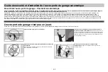
Page 43: ...e carefully and keep it for reference Check the operation of your garage door and opener to ensure they function in a safe and trouble free manner Be sure to read all Important Safety Information foun...

Page 44: ...t a trained door systems technician for assistance l Verify the photoeye height is no higher than 6 from the garage floor Test the door for proper operation l Open and close the door manually using ha...

Page 45: ...on Part Number 1 Curved door arm 041B0035B 2 Door bracket with clevis pin and fastener 041A5047 3 Emergency release rope and handle 041A2828 4 Header bracket with clevis pin and fastener 041A5047 2 5...

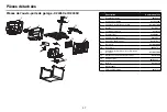
Page 46: ...panel with light socket 041A7760 4 Light socket 041C0279 5 Light lens 041 0144 6 Capacitor 030B0532 1 7 Capacitor bracket K012A0373 8 Travel module 041D7742 7 9 Cover 041 0228 000 10 Receiver logic b...

Page 47: ...panel with light socket 041 0037 000 4 Light socket 041C0279 5 Light lens 041 0144 6 Capacitor 030B0532 1 7 Capacitor bracket K012A0373 8 Travel module 041D7742 7 9 Cover 041 0028 000 10 Logic Board 0...

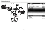
Page 48: ...el with light socket 041 0037 000 4 Light socket 041C0279 5 Light lens 041 0144 6 Capacitor 030B0532 1 7 Capacitor bracket K012A0373 8 Travel module 041D7742 7 9 Cover 041 0028 000 10 Logic Board 050A...

Page 49: ...d panel with light socket 041D8129 4 Light socket 041C0279 5 Light lens 041 0144 6 Capacitor 030B0532 1 7 Capacitor bracket K012A0373 8 Travel module 041D7742 7 9 Cover 041 0228 000 10 Logic Board 045...

Page 50: ...50...

Page 51: ...51...

Page 52: ...The Chamberlain Group Inc All Rights Reserved Wi Fi is a registered trademark of Wi Fi Alliance HomeLink is a registered trademark of Gentex Corporation The Chamberlain Group Inc 300 Windsor Drive Oa...

Page 53: ...ifs la s curit ci joints Fixez le manuel pr s de la porte de garage apr s l installation La porte NE SE FERMERA PAS si le Protector System n est pas connect et correctement align Des v rifications p r...

Page 54: ...tretien 39 D pannage 40 Garantie 42 Guidedes curit etd entretiendel ouvre portedegarageautomatique 43 Pi cesd tach s 45 Pi ces d assemblage des rails 45 Pi ces d installation 45 Mod le C2102C 46 Mod l...

Page 55: ...appelez un technicien qualifi en syst mes de porte 4 V rifiez le joint d tanch it au bas de la porte Tout cart entre le sol et le bas de la porte ne doit pas d passer 6 mm 1 4 po Sinon le syst me d i...

Page 56: ...t pour tester les capteurs d inversion de s curit l Support et mat riel de fixation Doit tre utilis si vous avez un plafond fini dans votre garage l Extension brackets Model 041A5281 1 or wood blocks...

Page 57: ...9 Supports de suspension 2 emball s l int rieur de la section de rail avant 10 Ouvre porte de garage bloc moteur 11 carteur de cha ne avec vis Mod le C2405 12 Support en U 13 Cha ne et c ble ou cha n...

Page 58: ...10 24 2 crou 5 16 po 18 6 Vis autotaraudeuse 1 4 po 14 x 5 8 po 2 Axe paulement 5 16 po x 1 po Axe paulement 5 16 po x 1 1 4 po Rondelle d arr t 5 16 po 18 5 crou oreilles 2 Anneau de fixation 3 COMM...

Page 59: ...u rail retirez soigneusement le bras de porte droit rang dans la section du rail 2 Alignez les sections de rail sur une surface plane tel qu indiqu et faites glisser les extr mit s coniques dans les p...

Page 60: ...cle l arri re du rail tel qu illustr Serrez fermement avec un contre crou 1 4 po 20 NE PAS trop serrer 2 Retirez les boulons du haut du bloc moteur 3 Utilisez le carton pour soutenir l extr mit avant...

Page 61: ...eur doit tre pr graiss S il est sec regraissez le pour vous assurer de son bon fonctionnement 3 Placez la poulie de tension dans la fen tre tel qu indiqu 4 Ins rez le boulon de tension par le haut tra...

Page 62: ...ser l extr mit ferm e du ressort clipser sur l une des broches Poussez l extr mit ouverte du ressort clipser sur l autre goupille 3 Avec le chariot contre le tournevis faites passer le reste du c ble...

Page 63: ...t pas suffisamment tendue Lorsque l installation est termin e il est possible que la cha ne pende un peu quand la porte est ferm e Ceci est normal Si la cha ne revient dans la position illustr e lorsq...

Page 64: ...ce d alimentation avant d y tre invit 8 NE portez JAMAIS de montres bagues ou v tements amples en installant ou entretenant l ouvre porte Ils pourraient tre happ s dans les m canismes de porte de gara...

Page 65: ...avec rail horizontal Porte Porte monobloc sans rail mat riel de fixation pivotant Porte Pivot TAPE 1 D terminer l emplacement du support de linteau Les proc dures d installation varient selon les type...

Page 66: ...TION B INSTALLATION AU PLAFOND 1 tendez la ligne m diane verticale sur le plafond tel qu indiqu 2 Centrez le support sur la marque verticale un espacement maximum de 15 cm 6 po du mur V rifiez que la...

Page 67: ...nez le support de rail contre le support de linteau 3 Alignez les trous du support et joignez les avec un axe paulement tel qu illustr 4 Ins rez un anneau de fixation pour s curiser TAPE 4 Positionner...

Page 68: ...staller l ouvre porte de garage 2 Assurez vous que l ouvre porte de garage est align avec le support de linteau Mesurez la distance entre chaque c t de l ouvre porte de garage et le support 3 Coupez l...

Page 69: ...les obstacles aient t retir s du trajet qu elle suivra l N utilisez JAMAIS la poign e pour ouvrir ou fermer la porte Si le n ud de la corde se d fait vous risquez de tomber 1 Ins rez une extr mit de...

Page 70: ...m 2 et 4 po sous le bord sup rieur de la porte OU directement sous tout support structurel du dessus de la porte 3 Marquez des trous et percez les puis proc dez l installation comme suit selon la cons...

Page 71: ...iel non fourni TAPE 8 Installer le support de porte suite OPTION B PORTES MONOBLOC 1 Centrez le support de porte sur le dessus de la porte en ligne avec le support de linteau tel qu illustr 2 Marquez...

Page 72: ...s l aide des boulons des crous et des rondelles d arr t 5 Tirez la poign e de d clenchement d urgence vers l ouvre porte de garage jusqu ce que le bras de d clenchement du chariot soit horizontal Le c...

Page 73: ...u chariot l aide de l axe paulement Fixez avec l anneau de fixation 5 Tirez la poign e de d clenchement d urgence vers l ouvre porte de garage jusqu ce que le bras de d clenchement du chariot soit hor...

Page 74: ...gl e et qu il n y a pas d obstacles au d placement de la porte l Gardez TOUJOURS la porte de garage en vue jusqu ce qu elle soit compl tement ferm e Ne permettez JAMAIS quiconque de passer la ligne d...

Page 75: ...de toute autre surface de marche adjacente et loin de TOUTES les pi ces mobiles de la porte Pour les installations d une bo te de commande il n est pas n cessaire de percer des trous ou d installer de...

Page 76: ...11 mm 7 16 po d isolant l extr mit du fil pr s de l ouvre porte de garage 3 Connectez le fil aux bornes rouge et blanche de l ouvre porte de garage Si votre garage est pr c bl veillez utiliser les m m...

Page 77: ...rt de capteur autour du bord du rail de porte Enclenchez le de mani re ce que le support du capteur affleure le rail 2 Faites glisser la vis six pans travers le capteur 3 Fixez le capteur au support a...

Page 78: ...vec deux tirefonds non fournis 2 Faites glisser la vis six pans travers le capteur 3 Fixez le capteur au support avec l crou oreilles V rifiez que l objectif n est pas obstru par le support R p tez le...

Page 79: ...le fil des deux capteurs l ouvre porte de garage Fixez avec des agrafes mais NE percez PAS le fil 2 S parez les fils du capteur et d nudez l isolant chaque extr mit Torsadez les deux fils blancs ensem...

Page 80: ...fils du capteur et d nudez l isolant chaque extr mit Choisissez deux des fils pr install s et d nudez l isolant chaque extr mit Choisissez les fils pr install s de la m me couleur pour chaque capteur...

Page 81: ...nt dans une prise de terre Si la fiche ne rentre pas dans la prise communiquez avec un lectricien qualifi pour faire installer une prise ad quate Installation TAPE 15 Connecter l alimentation IL EXIST...

Page 82: ...T Si l un des deux voyants des capteurs est teint le capteur n est pas aliment 1 V rifiez que l ouvre porte de garage est aliment en lectricit 2 V rifiez que le fil du capteur n est pas court circuit...

Page 83: ...grammation Les boutons de programmation sont situ s sur le panneau lat ral gauche de l ouvre porte de garage et sont utilis s pour programmer le d placement Pendant la programmation les boutons fl ch...

Page 84: ...te de garage clignoteront deux fois et le bouton fl ch vers le BAS commencera clignoter 4 Appuyez et maintenez le bouton fl ch vers le BAS jusqu ce que la porte soit dans la position BASSE souhait e 5...

Page 85: ...pouce ou un 2x4 pos plat sur le sol centr e sous la porte du garage 2 La porte tant compl tement ouverte placez une planche de 3 8 cm 1 1 2 pouce ou un 2x4 pos plat sur le sol centr e sous la porte du...

Page 86: ...ll e 1 V rifiez que votre appareil mobile poss de le plus r cent logiciel 2 T l chargez la derni re version de l application myQ Pour plus d information sur la connexion de votre ouvre porte de garage...

Page 87: ...iel qui sont TOUS sous une tension EXTR ME DOIVENT tre effectu es par un technicien en syst mes de portes qualifi 13 D branchez TOUJOURS l alimentation lectrique de l ouvre porte de garage AVANT d eff...

Page 88: ...POUSS E Appuyez sur la barre de pouss e pour ouvrir ou fermer la porte BOUTON LEARN apprentissage Utilisez le pour programmer des t l commandes compatibles des entr es sans cl sans fil et des disposi...

Page 89: ...votre porte de garage Entr e sans cl Entrez un num ro d identification personnel NIP 4 chiffres de votre choix sur le clavier du dispositif d entr e sans cl Ensuite appuyez et maintenez le bouton ENTE...

Page 90: ...LS Y COMPRIS les accessoires compatibles myQ 1 Appuyez et maintenez le bouton LEARN apprentissage sur l ouvre porte jusqu ce que le voyant DEL LEARN s teigne environ 6 secondes 2 Appuyez imm diatement...

Page 91: ...appareil de l quipement ou du r cepteur l Brancher l quipement sur une prise correspondant un autre circuit que celui sur lequel le r cepteur est branch l Consulter le revendeur ou un technicien radio...

Page 92: ...y a des obstructions comme un ressort bris ou le dispositif de verrouillage et corrigez la situation au besoin Remplacez la carte m re si n cessaire L ouvre porte met un son de bourdonnement pendant 1...

Page 93: ...all s et align s correctement et qu ils ne sont pas obstru s o Si le capteur de r ception voyant DEL vert fait directement face la lumi re du soleil changez le capteur de r ception avec le capteur d e...

Page 94: ...E TACITE DE QUALIT COMMERCIALE ET D ADAPTATION UNE QUELCONQUE UTILISATION EST LIMIT E LA DUR E DE LA GARANTIE LIMIT E CI DESSUS POUR LES PI CES CONNEXES ET LES GARANTIES NON TACITES EXISTERONT OU SERO...

Page 95: ...rifiez le fonctionnement de votre porte de garage et de votre ouvre porte pour vous assurer qu ils fonctionnent de fa on s curitaire et sans probl me Assurez vous de lire toutes les donn es importante...

Page 96: ...de portes pour obtenir de l aide l V rifiez la hauteur du capteur photo lectrique pour qu il ne se trouve pas une hauteur de plus de 2 m du sol du garage Effectuez un test de la porte pour v rifier qu...

Page 97: ...ce 1 Bras de porte incurv 041B0035B 2 Support de porte axe paulement et attache 041A5047 3 Corde et poign e de d clenchement d urgence 041A2828 4 Support de linteau avec axe paulement et fixation 041A...

Page 98: ...lairage 041A7760 4 Douille d clairage 041C0279 5 Lentille d clairage 041 0144 6 Condensateur 030B0532 1 7 Support de condensateur K012A0373 8 Module de d placement 041D7742 7 9 Couvercle 041 0228 000...

Page 99: ...douille 041 0037 000 4 Douille 041C0279 5 Lentille de la lumi re 041 0144 6 Condensateur 030B0532 1 7 Support du condensateur K012A0373 8 Module de d placement 041D7742 7 9 Cache vis 041 0028 000 10 C...

Page 100: ...ouille 041 0037 000 4 Douille 041C0279 5 Lentille de la lumi re 041 0144 6 Condensateur 030B0532 1 7 Support du condensateur K012A0373 8 Module de d placement 041D7742 7 9 Cache vis 041 0028 000 10 Ca...

Page 101: ...rage 041D8129 4 Douille d clairage 041C0279 5 Lentille d clairage 041 0144 6 Condensateur 030B0532 1 7 Support de condensateur K012A0373 8 Module de d placement 041D7742 7 9 Couvercle 041 0228 000 10...

Page 102: ...50...

Page 103: ...51...

Page 104: ...021 The Chamberlain Group Inc Tous droits r serv s Wi Fi est une marque d pos e de Wi Fi Alliance HomeLink est une marque d pos e de Gentex Corporation The Chamberlain Group Inc 300 Windsor Drive Oak...

Reviews: