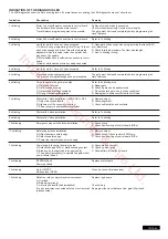
FUNCTIONALITY OVERVIEW OF THE PUSH BUTTONS P1, P2, P3 & RESET
P1+P2+P3
P1
P1 + P2
P2 + P3
P1 + P3
P2
P3
DIP „RADIO“ + P1
DIP „RADIO“ + P2
RESET
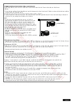
Manual operation. The gate wings can be moved electrically in a manual mode. Activate Function: Push P1+P2+P3
simultaneously. The LED LEARN starts to
fl
ash as long as feature is activated. Button P1 operates Motor1. Button P2 operates
Motor2. Deactivate: Wait for 20 seconds or disconnect logic board power. If wings close at
fi
rst reverse wires red and blue.
For automatic programming of the automatic travel distance limits of the gate.
For the advanced programming of the travel distance limits of the gate
Electric lock delay time
Wing delay adjustment.
Automatic closing time. Requires also P2 to con
fi
rm.
Software-reset to factory defaults. Push & hold for 10 seconds. Does not reset the remote control memory (see section “radio”).
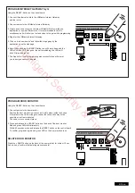
Programming Remote for Channel 1. Command for both motors (wings)
Programming Remote for Channel 2. Command for single motor (Motor1).
Program Internet Gateway or Door Monitor Note: The RESET button does not perform a reset of this particular control board
to factory defaults . It is only meant to program the Internet Gateway and the Door Monitor. See function P3 for resetting the
board to factory default settings.
Button
Function
6/16 en
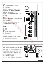
DESCRIPTION OF TERMINALS
DESCRIPTION FUNCTION
L
connector L 230V supply
N
connector N 230V supply
30VDC
connector for an external battery
Motor MASTER motor 1 (master opens
fi
rst) red/blue
Motor SECOND motor 2 (Second opens second) red/blue
To check correct polarity refer to section basic setting and
functionality P1+P2+P3 & RESET
24V/150mA
fl
ashing light (accessory)
Motor1 MASTER
BRN
brown cable
GRN
green cable
WHT
white cable
YEL
yellow cable
Motor2 SECOND
BRN
brown cable
GRN
green cable
WHT
white cable
YEL
yellow cable
Light Contact
gate monitor/ yard lighting
PED
key switch
COM
negative pole
STOP
stop switch
Key symbol
key switch
COM
negative pole
PHOTO3
photocells 3 (open)
PHOTO2
photocells 2 (close & open)
PHOTO1
photocells 1 (close)
COM
negative pole
EDGE
safety edge with 8.2KOhms
8.2kOhms
E-lock symbol
connection for E-lock control board
INPUT 24VAC
24V power input from transformer.
can be connected with any polarity.
Transformer 230VAC 230V supply to transformer. Can be
connected with any polarity.
250V/2A
fuse 250V/2A fast-blow (2x included)
DESCRIPTION OF LED´S (LIGHT EMITTING DIODE)
DESCRIPTION COLOUR
STATUS
Stop
green
Stop Switch
ON:
Stop
Active
OFF: OK (Requires wire bridge if
no
switch
is
connected)
Edge
green
Safety Edge 8.2KOhm
ON:
Activated
OFF:
OK
(Requires
8.2KOhm
resistor
if
not
used)
“Key symbol”
red
Key-switch 2-wing opening
ON:
Activated
OFF:
OK
PED
red
Key-switch 1-wing opening
ON:
Activated
OFF:
OK
PHO 1
red
Photocell 1 (close)
ON:
OK,
photocell
connected
(no
problem)
OFF:
No
photocells
connected
PHO 2
red
Photocell 2 (open & close)
(Refer
to
photocell
1)
PHO 3
red
Photocell 3 (open)
(Refer
to
photocell
1)
LEARN
yellow
Programming indicator
ON:
(
fl
ashing)
programming
is
active
OFF:
off
DGN
red
Diagnostic, Refer to page 15
CH1
red
Remote control
programming
2-wing
opening
ON: New remote can be
programmed
OFF:
off
CH2
red
Remote control programming
1-wing opening (Refer to CH1)
Intelligent Security & Fire Ltd.


