background image

S A F E T Y   I N S T A L L A T I O N   I N F O R M A T I O N

4

4

1. Vehicular gate systems provide convenience and security. Gate systems are comprised of many component parts. The gate

operator is only one component. Each gate system is specifically designed for an individual application.

2. Gate operating system designers, installers and users must take into account the possible hazards associated with each individual

application. Improperly designed, installed or maintained systems can create risks for the user as well as the bystander. Gate
systems design and installation must reduce public exposure to potential hazards.

3. A gate operator can create high levels of force in its function as a component part of a gate system. Therefore, safety features

must be incorporated into every design. Specific safety features include:
• Gate Edges

• Guards for Exposed Rollers

• Photoelectric Sensors

• Screen Mesh

• Vertical Posts

• Instructional and Precautionary Signage

4. Install the gate operator only when:

a. The operator is appropriate for the construction and the usage class of the gate.

b. All openings of a horizontal slide gate are guarded or screened from the bottom of the gate to a minimum of 4' (1.2 m) above

the ground to prevent a 2 1/4" (6 cm) diameter sphere from passing through the openings anywhere in the gate, and in that
portion of the adjacent fence that the gate covers in the open position.

c. All exposed pinch points are eliminated or guarded, and guarding is supplied for exposed rollers.

5. The operator is intended for installation only on gates used for vehicles. Pedestrians must be supplied with a separate access

opening. The pedestrian access opening shall be designed to promote pedestrian usage. Locate the gate such that persons will not
come in contact with the vehicular gate during the entire path of travel of the vehicular gate. 

6. The gate must be installed in a location so that enough clearance is supplied between the gate and adjacent structures when

opening and closing to reduce the risk of entrapment. Swinging gates shall not open into public access areas.

7. The gate must be properly installed and work freely in both directions prior to the installation of the gate operator.

8. Controls intended for user activation must be located at least six feet (6') away from any moving part of the gate and where the

user is prevented from reaching over, under, around or through the gate to operate the controls.  Outdoor or easily accessible
controls shall have a security feature to prevent unauthorized use.

9. The Stop and/or Reset (if provided separately) must be located in the line-of-sight of the gate. Activation of the reset control shall

not cause the operator to start.

10. A minimum of two (2) WARNING SIGNS shall be installed, one on each side of the gate where easily visible. 

11. For a gate operator utilizing a non-contact sensor:

a. Reference owner’s manual regarding placement of non-contact sensor for each type of application.

b. Care shall be exercised to reduce the risk of nuisance tripping, such as when a vehicle trips the sensor while the gate is  still

moving.

c. One or more non-contact sensors shall be located where the risk of entrapment or obstruction exists, such as the perimeter

reachable by a moving gate or barrier.

12. For a gate operator utilizing a contact sensor such as an edge sensor:

a. One or more contact sensors shall be located where the risk of entrapment or obstruction exists, such as at the leading edge,

trailing edge and post mounted both inside and outside of a vehicular horizontal slide gate.

b. One or more contact sensors shall be located at the bottom edge of a vehicular vertical lift gate.

c. A hard wired contact sensor shall be located and its wiring arranged so the communication between the sensor and the gate

operator is not subject to mechanical damage.

d. A wireless contact sensor such as the one that transmits radio frequency (RF) signals to the gate operator for entrapment

protection functions shall be located where the transmission of the signals are not obstructed or impeded by building structures,
natural landscaping or similar obstruction. A wireless contact sensor shall function under the intended end-use conditions.

e. One or more contact sensors shall be located on the inside and outside leading edge of a swing gate. Additionally, if the bottom

edge of a swing gate is greater than 6" (152 mm) above the ground at any point in its arc of travel, one or more contact sensors
shall be located on the bottom edge.

f. One or more contact sensors shall be located at the bottom edge of a vertical barrier (arm).

Summary of Contents for Elite SL3000UL

Page 1: ...E R S M A N U A L S L 3 0 0 0 U L VEHICUL AR SLIDE GATE OPERATOR THE SL3000UL IS FOR USE ON VEHICULAR PASSAGE GATES ONLY AND NOT INTENDED FOR USE ON PEDESTRIAN PASSAGE GATES UL325 compliant UL991 comp...

Page 2: ......

Page 3: ...ion Device Locations 6 7 INSTALLATION Installation Setups 8 Safety Catch Rollers and Gate Rail Stops 9 Mounting Operator 10 Chain Installation 11 Control Board Description 12 Surge Suppressor Terminal...

Page 4: ...000 120 Vac 4 Amp Heater 3 Amp Maximum Gate Length 37 ft Maximum Gate Weight 1000 lbs Maximum Pull 105 lbs SL3000ULDM Dual Motor Two 1 2 hp Motors 120 Vac 4 7 Amp Maximum Gate Length 37 ft Maximum Gat...

Page 5: ...n That means that the installation must have one primary means of entrapment protection and one independent secondary means of entrapment protection Both primary and secondary entrapment protection me...

Page 6: ...gate operator 8 Controls intended for user activation must be located at least six feet 6 away from any moving part of the gate and where the user is prevented from reaching over under around or thro...

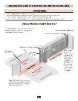
Page 7: ...BOTH sides of EACH gate in PLAIN VIEW WARNING To prevent SERIOUS INJURY or DEATH from a moving gate Entrapment protection devices MUST be installed to protect anyone who may come near a moving gate Lo...

Page 8: ...the open and close gate cycles Locate entrapment protection devices to protect between moving gate and RIGID objects such as posts or walls WARNING Install photo electric sensors to protect against a...

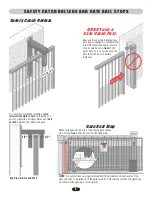
Page 9: ...G Install edge sensors to protect against any entrapment or safety conditions encountered in your gate application See Entrapment Protection Devices Safety loops allows the gate to stay open when vehi...

Page 10: ...37 ft Maximum gate length with long gate kit 51 ft Maximum gate weight varies for operators Maximum gate length 37 ft for each gate Maximum gate weight varies for operators High Voltage UL approved co...

Page 11: ...ance of half an inch between the rollers and gate NOTE For safety reasons physical stops MUST be installed on both ends of the gate rail prior to installation of the gate operator This will assure tha...

Page 12: ...d Below the frost line Check all local codes High voltage conduit Low voltage conduit Suggested installation for dirt ground The measurements depend on the type of ground ie asphalt cement dirt Check...

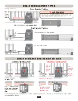
Page 13: ...gate Operator is mounted too close and not parallel to gate INCORRECT INSTALLATION CORRECT INSTALLATION CHAIN DISTANCE AND HEIGHT ON GATE CHAIN INSTALL ATION T YPES 2 inch wire grid safety screen is...

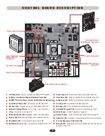
Page 14: ...8 Gate Opening Direction Selector Open Left Open Right Gate Locked LED Maglock Solenoid is activated when on Reset Motor LED Cycle operator power when ON Radio Receiver LED Radio transmitter is activa...

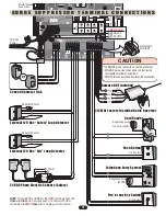
Page 15: ...with a single push of a button Output Power Ground 24 VDC Remote NOT Included 315 MHz Factory Installed Radio Receiver Dry Contact Dry Contact Separate power for card reader Separate Power Separate Po...

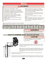
Page 16: ...ING Proper grounding gives an electrical charge such as from an electrical static discharge or a near lightning strike a path from which to dissipate its energy safely into the earth Without this path...

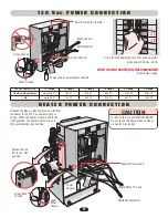
Page 17: ...d Dual Motor 1 HP 16 Gauge up to 150 FT up to 75 FT 14 Gauge 250 FT 125 FT 12 Gauge 400 FT 200 FT 10 Gauge 650 FT 325 FT 8 Gauge 1000 FT 500 FT 4 Gauge 2200 FT 1100 FT 1 2 0 V a c P O W E R C O N N E...

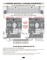
Page 18: ...FIR DEPT STRI OPEN RAD RECE VER EX T LOOP REVERSE SENSOR SAFETY LOOP CENTER LOOP GAT LOCKED RESET MOTOR COMMAND PROCESSED CHASSIS GROUND Run low voltage 16 18 gauge wire in UL approved conduit to link...

Page 19: ...MOTOR 3 3 CO A D PROCESSED ON G B MS LINK A MADE IN USA Solenoid Lock Normally Closed Normally Open Optional Relay Adapter Module Optional Relay Adapter Module Common Common Plug In Transformer Solen...

Page 20: ...nterlock wires Do Not Remove Push and Hold to operate gate Gate automatically opens Turn the 120 Vac power off then push and Hold to operate gate Turn the 120 Vac power off then gate opens automatical...

Page 21: ...rect Fire Police emergency key access D C 2 0 0 0 S a f e t y D e v i c e s It is recommended using separate safety devices to maintain gate safety when the DC2000 is needed for any reason The safety...

Page 22: ...etector manual for more specific information Plug In Safety Loop Detector Allows gate to stay open when vehicles are obstructing path Caution Suggested for vehicles 14 feet or longer If the Inside and...

Page 23: ...me number of wire turns See table below 120 Vac Exit Loop Detector Allows gate to automatically open for exiting vehicles See Accessories 10 feet to 13 feet 14 feet to 26 feet 27 feet to 80 feet 80 fe...

Page 24: ...Connect all edge sensors to the sensor connection To prevent SERIOUS INJURY or DEATH from a moving gate Locate entrapment protection devices to protect in BOTH the open and close gate cycles Locate en...

Page 25: ...EPT STR KE OPEN RADIO RECE VER TIMER SYSTEM ON EX T LOOP ALARM SENSOR REVERSE SENSOR OPEN CLOSE SAFETY LOOP CENTER LOOP GATE LOCKED 6 POWER OVERLOAD OFF W4 OPEN LEFT DC BACKU AL RM SENSOR N HT 3 SENSO...

Page 26: ...d B A W4 W G O M N I O P T I O N B O A R D C O N N E C T I O N S Purchased separately from Chamberlain Elite See Accessories NOTE Cut jumper W4 wire for 3 button station or stop button Stop Button Dry...

Page 27: ...CKUP ALARM SENSOR O R GHT 3 SENSORS RESET MOTOR 3 CO A D PROCESSED ON G B MS LINK A MADE IN USA RADIO MER 60 OFF 1 3 ON OPEN RIGHT RADIO MER 60 OFF 1 3 ON OPEN LEFT Push and hold lock plate to release...

Page 28: ...ons the receiver can be set to either C constant or M momentary closure With the jumper in the M momentary position the contacts will close for 1 4 second regardless of the length of remote control tr...

Page 29: ...rased Reprogram each remote you wish to use IMPORTANT Hand Held Remote NOT Included NOTE Receiver wiring on Surge Suppressor Terminal Connections page Disconnect the second receiver when using a maste...

Page 30: ...ion Push button once to open gate push button again to close gate Set Timer 1 to 60 seconds 1 Turn Master Timer ON 2 Turn Second Timer OFF 3 Use Timer on Master Board Only 1 to 60 seconds Master Board...

Page 31: ...n the weight of the gate and the condition of installation Sensor is set too sensitive if the gate stops in midcycle or reverses by itself Sensor is not set sensitive enough if the gate hits an object...

Page 32: ...ltmeter verify that the incoming voltage to the operator it is within ten percent of the operators rating 14 Verify all safety and entrapment devices are functioning IMPORTANT SAFETY INSTRUCTIONS To r...

Page 33: ...ch to Shut Off Alarm and Reset Operator See above Pressing the reset switch will stop a moving gate during a normal open close cycle like a stop button The operator does NOT need to be reset after doi...

Page 34: ...U A L R E L E A S E NOTE YOU may use a cordless power drill 6 sec for quicker opening in non emergency situations Push the crank tool in hole Safety releases will separate Turn the crank to open the...

Page 35: ...Sensing Edge Part G65MGS20x x length 4 5 6 8 ft e g G65MGS204 is 4 ft Accessories Relay Adapter Module Part Q400MAU For more information about accessories www chamberlain com Omni Option Board Part OO...

Page 36: ...Reset Switch Interlock Assembly Not Used to OmniControl Board J7 J9 1 2 3 4 5 6 J8 J2 J6 J5 J3 to OmniControl Board J2 J1 3 1234567 4 3 Chassis Ground Input Power 120 Vac 60 Hz Grounded J10 J10 Green...

Page 37: ...io Receiver 11 Radio Receiver 12 Radio Receiver 13 Not Used Not Used Safety External Loop Detector 3 Safety External Loop Detector 4 Exit External Loop Detector 5 Exit External Loop Detector 6 In In I...

Page 38: ...rol Board J7 J9 1 2 3 4 5 6 J8 J2 J6 J5 J3 to OmniControl Board J2 J1 3 1234567 4 3 Chassis Ground Input Power 120 Vac 60 Hz Grounded J10 J10 Green Ground OFF ON NOTE Reset switch and interlock assemb...

Page 39: ...adio Receiver 11 Radio Receiver 12 Radio Receiver 13 Not Used Not Used Safety External Loop Detector 3 Safety External Loop Detector 4 Exit External Loop Detector 5 Exit External Loop Detector 6 In In...

Page 40: ...rd J7 1 2 3 4 5 6 J8 J2 J6 J5 J3 to OmniControl Board J2 J1 3 1234567 4 3 2 4 6 Chassis Ground Input Power 120 Vac 60 Hz Grounded J10 J10 Green Ground OFF ON J11 J12 J13 1 2 3 Chassis Ground Radio Har...

Page 41: ...Used Safety External Loop Detector 3 Safety External Loop Detector 4 Exit External Loop Detector 5 Exit External Loop Detector 6 Motor Red Motor Black Motor White Neutral Motor Black Motor White Neutr...

Page 42: ...LOOP GATE LOCKED RESET MOTOR COMMAND PROCESSED Limit Box Assembly Left Right 12 VDC Motor Purple N C Green N C Green N C Black Shield 3 Red Red N O Red N O 4 Black Black Com Black Com Reset Switch DC2...

Page 43: ...Photo Beam Sensor 12 VDC J Direction Level 10 J Pin Input Connection Signal Type NOTE All devices wired to the DC2000 MUST be dedicated to it alone Normal operation will be controlled by separate dev...

Page 44: ...wer to the radio receiver 3 Probable Cause Radio receiver s signal is not getting to gate operator Solution Check wiring between receiver and surge suppressor 4 Probable Cause Remote is not programmed...

Page 45: ...back to your original setting 2 Verify and correct connections 3 Set a different working frequency 4 Decrease the sensitivity of the loop detector 1 Short circuit at terminals 11 and 13 2 Short circu...

Page 46: ...T R A T I O N S Q033 Q028 Q039 Q237 Q020 Q025 Q404 Q400D Q006 Q410 Q409 Q401 Q407 Q420 Q421 Q005 Q027 Q021 Q030 Q014 Q016 Q015 Q003 Q004 K23 51158 G6518SL Q408 K75 50893 Q254 Q029 Q018 312HM NOTE Sold...

Page 47: ...1 2 HP Electric Motor Q020 Drive Belt Q021 Gear Pulley Q025 Motor Pulley Q027 Motor Capacitor Q028 Manual Crank Q029 Limit Switch Q030 Limit Switch Chain Q039 Drive Belt DM and 1 HP Q237 Crank Input Q...

Page 48: ...46 System Diagram...

Page 49: ...ring operation it must stop or reverse depending on the direction gate is traveling 9 Make sure that any pinch point or potential entrapment are guarded by means of safety devices or like 10 Warning p...

Page 50: ...ED IN DURATION TO THE 7 YEAR RESIDENTIAL 5 YEAR COMMERCIAL LIMITED WARRANTY PERIOD SET FORTH ABOVE EXCEPT THE IMPLIED WARRANTIES WITH RESPECT TO THE SL3000UL WHICH ARE LIMITED IN DURATION TO THE 7 YEA...

Page 51: ......

Page 52: ...2008 The Chamberlain Group Inc All Rights Reserved 01 50388E 845 Larch Avenue Elmhurst Illinois 60126 1196 S L 3 0 0 0 U L UL325 compliant UL991 compliant...

Reviews: