background image

18

Three Phase

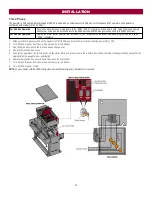
The operator is field configurable for usage at 208, 240, and 480 Vac. Factory default is 240 Vac. For three phase 575V operators, the operator is
configured at the factory for 575V ONLY.

For 208 Vac Operation

Ensure the motor harness is plugged in to the “208V / 240V” receptacle on the power board. Swap the orange and red
transformer wires (the red wire connects to the 240V position and the orange wire connects to the 208V position).

For 480 Vac Operation

Unplug the motor power harness from the“208V / 240V” receptacle on the power board and plug the harness into the
“480V” receptacle.

1. Make sure the AC power switch on the operator is OFF (the AC power switch will turn the incoming power ON or OFF).

2. Turn off the AC power from the main power source circuit breaker.

3. Run the AC power wires to the junction box on the operator.

4. Remove the junction box cover.

5. Connect the operator wires to line power via the white, black, and green wires in the junction box. Follow the table in the specification section for the

appropriate wire gauge for your application.

6. Replace the junction box cover. Ensure the wires are not pinched.

7. Turn on the AC power from the main power source circuit breaker.

8. Turn on the AC power switch.

NOTE:

To use a heater with the 480V configuration an additional step down transformer is required.

INSTALLATION

Summary of Contents for ELITE SL585101UL

Page 1: ...ster com to locate a professional installing dealer in your area This gate operator is compatible with MyQ and Security 2 0 accessories SL585101UL 1 HP 120 208 240 Vac Single Phase SL585103UL 1 HP 208...

Page 2: ...Gateway Not Provided 36 Erase All Codes 36 To Remove and Erase Monitored Entrapment Protection Devices 36 Constant Pressure Override CPO 36 SETTINGS 37 Gate Operator Setup Examples 37 Dual Gate Settin...

Page 3: ...ment protection devices in each entrapment zone l This vehicular slide gate operator will operate only after installation of a minimum of two independent monitored entrapment protection devices in eac...

Page 4: ...d and work freely in both directions prior to the installation of the gate operator 8 Permanently mounted access controls intended for users to activate must be located at least 6 feet 1 8 m away from...

Page 5: ...existing gate shall be upgraded to conform to the provisions of this specification 2 4 When the gate of an automated gate system requires replacement the new gate shall conform to the provisions of t...

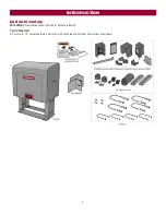
Page 6: ...ton Inventory NOT SHOWN Documentation Packet Chain 50 25 feet Eye Bolt Kit Tools Needed 3 4 wrench for 1 2 concrete anchors Screwdrivers Phillips head and flat head Cable cutters and strippers INTRODU...

Page 7: ...1 Phase and 3 Phase Cantilever 35 feet OH Roller 70 feet V Track 50 feet 1 1 2 HP 1 Phase Cantilever 40 feet OH Roller 75 feet V Track 55 feet Maximum Gate Travel Speed 1 foot second Maximum Daily Cy...

Page 8: ...480 Vac 3 Amps 575 Vac 1 8 Amps 1 1 2 Single 120 Vac 20 Amps 26 Amps including Accessory Outlets 208 240 Vac 10 Amps Accessory Outlets are rated for 120 Vac 6 Amps maximum NOTE The outlet is only avai...

Page 9: ...your gate application Install a warning sign two provided on the inside and outside of the property where easily visible Gate Gate must be constructed and installed according to ASTM F2200 standards...

Page 10: ...BEFORE digging more than 18 inches 46 cm deep l DO NOT touch the heater when switch is on heater may be hot l To prevent damage to the operator or gate DO NOT drive the limit nuts actuators on the sh...

Page 11: ...u have pad constrictions either angle can be unbolted and reversed to angle in NOTE If you are replacing an SL580 and wish to use the same pad mounting hardware the gate side mounting angle must be in...

Page 12: ...posts 24 1 8 61 cm to 26 66 cm outside to outside NOTE If you are replacing a SL580 the frame will require adjustment to 24 1 8 New installation 1 Locate and anchor two posts made of 3 7 6 cm outer di...

Page 13: ...n to the front bracket with the provided hardware Adjust nuts on chain take up bolts to remove chain slack A general rule of thumb is to leave a maximum of 1 2 5 cm of chain slack for every 10 3 1 m o...

Page 14: ...stallation is unique It is the responsibility of the installer to ensure that ALL entrapment zones are protected with an external monitored entrapment protection device protecting both the open and cl...

Page 15: ...edge sensor entrapment protection for the close direction When an obstruction is sensed during gate closing the gate will reverse to the full open position disengaging the Timer to Close This input w...

Page 16: ...a MUST be cleared and secured at that time the unit may be returned to service l Disconnect power at the fuse box BEFORE proceeding Operator MUST be properly grounded and connected in accordance with...

Page 17: ...F 2 Turn off the AC power from the main power source circuit breaker 3 Run the AC power wires to the junction box on the operator 4 Remove the junction box cover 5 Connect the operator wires to line p...

Page 18: ...to the 480V receptacle 1 Make sure the AC power switch on the operator is OFF the AC power switch will turn the incoming power ON or OFF 2 Turn off the AC power from the main power source circuit brea...

Page 19: ...low NETWORK LED will light 4 Press and release the OPEN test button to assign this operator as network primary 5 Press and release the LEARN button on the second operator The green XMITTER LED will li...

Page 20: ...he wires from the shielded twisted pair cable to the Com Link terminals on the primary gate operator control board NOTE We recommend that all accessories and board configurations are set on the primar...

Page 21: ...ashing If they are not flashing press and hold both the OPEN LEFT and OPEN RIGHT handing buttons until both handing LEDs start to flash and the operator beeps 2 Press and release either the OPEN RIGHT...

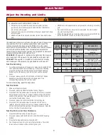
Page 22: ...the installation of the operator you must tighten the clutch spring lock nut so it is tight enough to operate the gate yet loose enough so that if the gate meets an obstruction the clutch will slip 1...

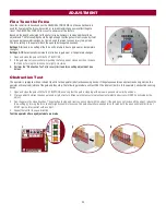
Page 23: ...slightly clockwise 3 Perform the Obstruction Test after every limit and force setting adjustment see below Obstruction Test The operator is equipped with an inherent built in to the operator obstructi...

Page 24: ...24 OPERATOR OVERVIEW...

Page 25: ...25 CONTROL BOARD OVERVIEW...

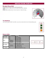
Page 26: ...ide gate will slide to the left when opening NOTE For gates installed on the outside of the property the setting will be opposite Determine the direction by looking towards the property from the outsi...

Page 27: ...iew the code history refer to the Troubleshooting section Status LEDs LED STATE DEFINITION INPUT POWER OFF OFF state ON AC power available TIMER OFF The timer is disabled ON The timer is enabled 1 bli...

Page 28: ...tary input logic as single button control and safeties remain active re enables Timer to Close Loops The Loop terminals are used for connecting loops and various control devices such as telephone entr...

Page 29: ...or close direction photoelectric sensors When an obstruction is sensed during gate closing the gate will open to the full open position This input will be disregarded during gate opening and resets th...

Page 30: ...cts a fault faults are ignored EXIT loop is faulted and inoperative AC FAIL Switch NOT USED ANTI TAIL Switch OFF When CLOSE EYES Interrupt loop is activated it causes a closing gate to stop and revers...

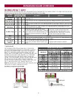
Page 31: ...and 3 LEDs will blink out the cycle count cycle count is stored on the control board See below Red green light functionality see below Cycle count First note the current Aux Relay switch positions To...

Page 32: ...itch settings located next to the terminals Switch set to CLOSE gate reverses fully when an obstruction is sensed Switch set to OPEN gate reverses 4 seconds when an obstruction is sensed EYE EDGE and...

Page 33: ...a closing gate and holds open an open gate SHADOW Loop wire connection for plug in loop detector when loop is positioned under the gate l Holds open gate at open limit l Disregarded during gate motion...

Page 34: ...ire and electrocution l DISCONNECT power AC or solar and battery BEFORE installing or servicing operator For continued protection against fire l Replace ONLY with fuse of same type and rating Field Wi...

Page 35: ...on depending on the desired function 3 Press the remote control button that you would like to program The operator will automatically exit learn mode operator will beep and green XMITTER LED will go o...

Page 36: ...lled through the LiftMaster Internet Gateway app Erase All Codes 1 Press and release the LEARN button operator will beep and green XMITTER LED will light 2 Press and hold the LEARN button again until...

Page 37: ...Secure indicator e g light Aux Relay Out Gate Motion Attach alert signal audible or visual alert system Attach alert signal audible or visual alert system Attach alert signal audible or visual alert...

Page 38: ...ose first Tandem Mode OFF Bi Part Delay OFF will open first and close last Tandem Mode OFF ACCESSORY PRIMARY OPERATOR SECONDARY OPERATOR Remote Controls Program remote controls 1 to 50 to the primary...

Page 39: ...sted and there are no obstructions to gate travel l SAVE THESE INSTRUCTIONS To protect against fire and electrocution l DISCONNECT power AC or solar and battery BEFORE installing or servicing operator...

Page 40: ...To Scroll Through the Saved Codes The operator will only keep track of up to 20 codes then will start saving over the oldest codes as new codes occur To Exit Press and release the STOP button to exit...

Page 41: ...rred AC DC board supply dipped below allowable level Review power supply and wiring If rebooting ensure enough time for discharge of power to force a fresh boot YES 54 Wireless Second Operator Communi...

Page 42: ...pen input EYE EDGE communication fault expansion board 84 Non monitored device detected on the wireless safety system Non monitored contact closure devices are not supported Make sure connected device...

Page 43: ...larm will sound up to 5 minutes and the operator will need to be reset A The gate is hitting a wall or vehicle B The gate does not meet specifications C Debris is on the gate s track such as mud rocks...

Page 44: ...obe active a Check all Open and Close inputs for a stuck on input b Check Stop button is not stuck on c Check Reset button d Check all Entrapment Protection Device inputs for a stuck on sensor e Check...

Page 45: ...operator that opens first Alarm beeps when running a Expansion board setting b Constant pressure to open or close is given a Pre warning is set to ON b Constant pressure to open or closed is given Exp...

Page 46: ...ter monitored through beam photoelectric sensor Model LMTBUL LiftMaster monitored retro reflective photoelectric sensor Model LMRRUL LiftMaster monitored wireless edge kit transmitter and receiver Mod...

Page 47: ...acket K10 3209 Take up Bolt K11 3503 Chain 50 Nickel Plated 25 K19 3025 Plastic Standoffs for main control board 10 per bag K77 37683 Heavy gate bracket for chassis 65 3509 ELECTRICAL BOX REPAIR PARTS...

Page 48: ...H ABOVE AND NO IMPLIED WARRANTIES WILL EXIST OR APPLY AFTER SUCH PERIOD Some states do not allow limitations on how long an implied warranty lasts so the above limitation may not apply to you THIS LIM...

Reviews: