background image

22

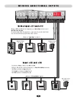
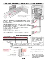
Wiring at 

#21

 and 

#22

 will be recognized as an 

Open Only

 command, and 

Will Not close the gate.


To automatically Close the gate after an open cycle, the control board timer 
must be turned ON. See page 26 about timer control.

Works as “

Open Only

” command.

Works as “

3 Push Button

” control.

To provide a 

Close

 command use 

#23

 and 

#24

.

Wiring at #23 and #24 will be recognized as a 

Three Push Button

 command. 

The 

First

 command will 

open

 the gate. 

The 

Second

 command will 

stop

 the gate. 

The 

Third

 command will 

close

 the gate.

Strike Input #21 and #22

Input #23 and #24

Separate Power

for Device

Separate Power

for Device

Separate Power

for Device

W I R I N G   A D D I T I O N A L   I N P U T S

Summary of Contents for Elite The Miracle-One

Page 1: ...IS FOR USE ON VEHICULAR PASSAGE GATES ONLY AND NOT INTENDED FOR USE ON PEDESTRIAN PASSAGE GATES MIRACLE ONE VEHICULAR ACTUATOR GATE OPERATOR The Chamberlain Group Inc 845 Larch Avenue Elmhurst Illinoi...

Page 2: ......

Page 3: ...8 Mounting Operator that Opens to the Outside 9 Mounting Operator that Opens to the Inside 10 Mounting Operator 1 13 Mounting Control Box 13 Mounting Operator s to Control Box 14 Control Board Descrip...

Page 4: ...Transformer 2 Warning Placards Warranty Card Battery Manual Accessory Kit Accessory Kit Control Box Assembly Master Second Control Box Assembly Single UL Alarm 34 Vdc 1 7 A Transformer Junction Box w...

Page 5: ...Can be set from 3 to 60 seconds or push open stop close operation Master Second Dictates synchronized movement between two gate operators Safety Loop Input Anti tailgating system uses a stop only meth...

Page 6: ...tant pressure control Type E Built in audio alarm Class I Class II Class III A B1 B2 or B2 A B1 D or E A B1 C or C A B1 C or D B2 A or C B1 B2 or D A UL325 Installation Classification Primary Type Sec...

Page 7: ...gate operator 8 Controls intended for user activation must be located at least six feet 6 away from any moving part of the gate and where the user is prevented from reaching over under around or thro...

Page 8: ...in BOTH the open and close gate cycles Locate entrapment protection devices to protect between moving gate and RIGID objects such as posts or walls A swinging gate shall NOT open into public access wa...

Page 9: ...tall on ANY pedestrian passageways or doorways DO NOT install on uphill or downhill gates If the Timer is to be left in the ON position then add safety loops and a center loop DO NOT install on ANY pe...

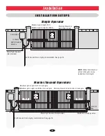
Page 10: ...See page 18 Earth Ground Rod is highly recommended See page 18 Junction Box Radio Receiver Antenna Control Box Master Second Maximum gate length 15 ft Maximum gate weight is 600 lbs Maximum gate leng...

Page 11: ...umn Setup Gate Hinge Gate Hinge Top View Heavy Steel Plate Typical Steel Post Setup Steel Re Bar Heavy Steel Plate for Reinforcement Not provided Indexing on center hole in the back steel bracket Inde...

Page 12: ...e Gate Hinge Typical Masonry Column Setup Gate Hinge Gate Hinge Top View Heavy Steel Plate Typical Steel Post Setup Steel Re Bar 10 Minimum Heavy Steel Plates for Reinforcement Not provided Heavy Stee...

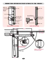
Page 13: ...or it will not function properly An off level installation may cause the gate or operator to fail prematurely The Miracle One can be mounted on top of the gate frame Unscrew 4 screws on top of operat...

Page 14: ...round the brackets and plates on the gate The gate must be in the closed position Make sure the operator is kept level while tack welding the front and back brackets and reinforcement steel plates in...

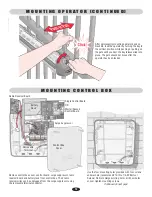
Page 15: ...ntrol box cover control board surge suppressor radio receiver board and battery rack from control box The 3 radio receiver wires can be unplugged from the surge suppressor using the removable terminal...

Page 16: ...embly Flexible Conduit See Above Second Water Tight Conduit Not provided Shielded Low Voltage Cable Junction Box with Cover Terminal Connector Bushing NOTE Reinstall all components back into control b...

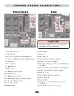
Page 17: ...se LED 15 Batteries Low LED 16 Charge OK LED 17 Power LED 18 Timer Active LED 19 Timer Adjustment 3 to 60 sec See page 26 20 Switch Timer Off On See page 26 21 Close Delay Overlapping Gate Off On Mast...

Page 18: ...13 14 Proximity Switch Normally Open Part APRS Refer to Page 21 Refer to Page 19 Refer to Page 19 13 14 Removable Terminal Connectors Com N O Ground NOTE You MUST use Shielded Wire for the blue and g...

Page 19: ...Refer to Page 22 24 Vdc Exit Loop Works as 3 Push Button Control Solar Power 34 Vdc 1 7 A Transformer Polarity does not matter 24 Volt Red Part CPSN4 N O Com Brown Wires Digital Lock Card Reader Key S...

Page 20: ...SENSOR LAKE FOREST CALIFORNIA www eliteaccess com REV A MIRACLE SURGE PROTECTION 1 2 3 4 5 6 7 8 9 10 11 12 13 14 15 16 17 18 19 20 21 22 23 24 25 26 27 Proper grounding gives an electrical charge suc...

Page 21: ...second operator To ENSURE proper operation of external devices ENSURE bare wires make good contact inside removable terminal connections DO NOT let wire insulation interfere with connection To prevent...

Page 22: ...ansformer 120 Vac 60 Hz Earth Ground Rod Highly Recommended See page 18 Use 14 gauge 300 watt direct burial landscape lighting wire NOT to exceed 500 ft Use 10 gauge wire up to 1000 ft Not provided Pl...

Page 23: ...trol box to protect it from the weather The control board provides a relay with a normally open contact to interface with a house alarm When interfacing with a house burglar alarm you must install pos...

Page 24: ...en Only command Works as 3 Push Button control To provide a Close command use 23 and 24 Wiring at 23 and 24 will be recognized as a Three Push Button command The First command will open the gate The S...

Page 25: ...eet to 13 feet 14 feet to 26 feet 27 feet to 80 feet 80 feet and up 4 3 2 1 The wire is continuously wound in the loop saw cut for the required number of turns One turn shown Refer to table Recommende...

Page 26: ...ectric sensors when the gate opens to less than 18 from a wall or any other object or potential entrapment installation If you are going to use a non contact sensor as a secondary entrapment protectio...

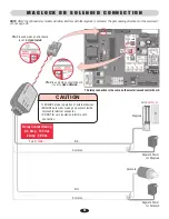
Page 27: ...used when control board is set to Open Outside Solenoid Maglock Common To ENSURE proper operation of external devices ENSURE bare wires make good contact inside removable terminal connector DO NOT let...

Page 28: ...t Timer 3 to 60 seconds NOTE If a secondary safety sensor device is NOT used when the timer is ON the gate WILL hit a vehicle obstructing the gate path during the close cycle Gate Opens Inward Gate Op...

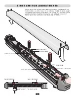
Page 29: ...ches of each armature to stop the gate in the full open and full closed positions See illustration below Re tighten armature screws when gate positions are correct Replace operator cover with 4 screws...

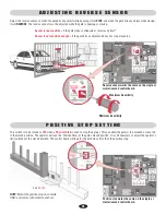
Page 30: ...stop NOTE Mount the positive stop on concrete ONLY and secure with concrete anchors Adjust the reverse sensor so when the gate hits any object while opening it will STOP and when the gate hits any obj...

Page 31: ...NLY when it can be seen clearly is properly adjusted and there are no obstructions in gate s path ALWAYS keep gate in sight until completely closed NEVER permit anyone to cross path of a moving gate T...

Page 32: ...erlap positioned on the Inside When Close Delay is turned ON the Master operator will delay closing it s gate to compensate for the gate overlap It works for any opening direction and overlap position...

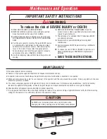
Page 33: ...LL INSTRUCTIONS 2 NEVER let children operate or play with gate controls Keep the remote control away from children 3 ALWAYS keep people and objects away from the gate NO ONE SHOULD CROSS THE PATH OF T...

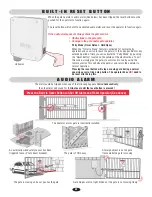
Page 34: ...the gate frame while the gate is moving Press the Built In Reset Button to Shut Off Alarm and Reset Operator See above Pressing the reset button will stop a moving gate during a normal open close cyc...

Page 35: ...se to Unlock the operator from the gate Step 2 Move the gate manually to the full open position 90 Step 3 Re Lock the operator by turning the key clockwise while pushing or pulling on the gate until y...

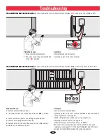
Page 36: ...new remote control battery Cycle the power to the radio receiver Remote control will need to be reprogrammed see page 29 Check wiring between receiver and surge suppressor Reprogram remote control se...

Page 37: ...e of the board and replace if necessary For technical support 1 800 528 2806 35 T R O U B L E S H O O T I N G C O N T I N U E D If left side board fuse is blowing on a regular basis make sure operator...

Page 38: ...ITS GREEN BLACK MOTOR WHITE RED BRAKE BROWN BLUE LIMITS GREEN CENTER LOOP 24 VAC INPUT SAFETY LOOP STRIKE INPUT BURGLAR ALARM INPUT GROUND RADIO 24 VOLT UL SENSOR LAKE FOREST CALIFORNIA www eliteacces...

Page 39: ...ce Connection Signal Type NOTE See diagram on previous page Single Surge Suppressor Reset Button Red Reset Button Black Limits Green Limits Blue Brake Brown Brake Red Motor White Motor Black Battery R...

Page 40: ...38 WIRING DIAGRAM MIRACLE ONE MASTER SECOND NOTE See table on next page...

Page 41: ...Input Brake Brown Wire Input Limits Blue Wire Input Limits Green Wire Input Motor Black Wire Input Motor White Wire Input Brake Red Wire Input Brake Brown Wire Input Limits Blue Wire Input Limits Gre...

Page 42: ...LIM ITS GREEN CENTER LOOP 24 VAC INPUT SAFETY LOOP STRIKE OPEN BURGLAR ALARM INPUT GROUND RADIO 24 VOLT UL SENSOR 1 2 3 4 5 6 7 8 9 10 11 12 13 14 15 16 17 18 19 20 21 22 23 24 25 26 27 BLACK MOT OR...

Page 43: ...14 Q239 Limit Switch Harness Wires and 4 Limit Switches 16 Q243 8 Amp Fuse Single 17 Q257 Replacement Key Lock Operator Made Post 3 14 99 18 Q258 Fuse 2 Amp Single 19 Q259 Fuse 3 Amp M S 20 Q260 15 Am...

Page 44: ...nges Maglock Solenoid Relay Adapter Module Page 25 Part Q240MAU 24 Vdc Photo Sensors Page 24 Part CPSN4 Accessories For more information about accessories www liftmaster com Part 371LM Part 372LM Part...

Page 45: ...E AND NO IMPLIED WARRANTIES WILL EXIST OR APPLY AFTER SUCH PERIOD Some States do not allow limitations on how long an implied warranty lasts so the above limitation may not apply to you THIS LIMITED W...

Page 46: ...ns and closes as needed Page 26 9 When gate hits object during operation it must stop or reverse direction Page 28 10 Know how to operate the emergency manual release with the key Page 33 11 Make sure...

Page 47: ......

Page 48: ...01 50593B 2011 The Chamberlain Group Inc All Rights Reserved...

Reviews: