background image

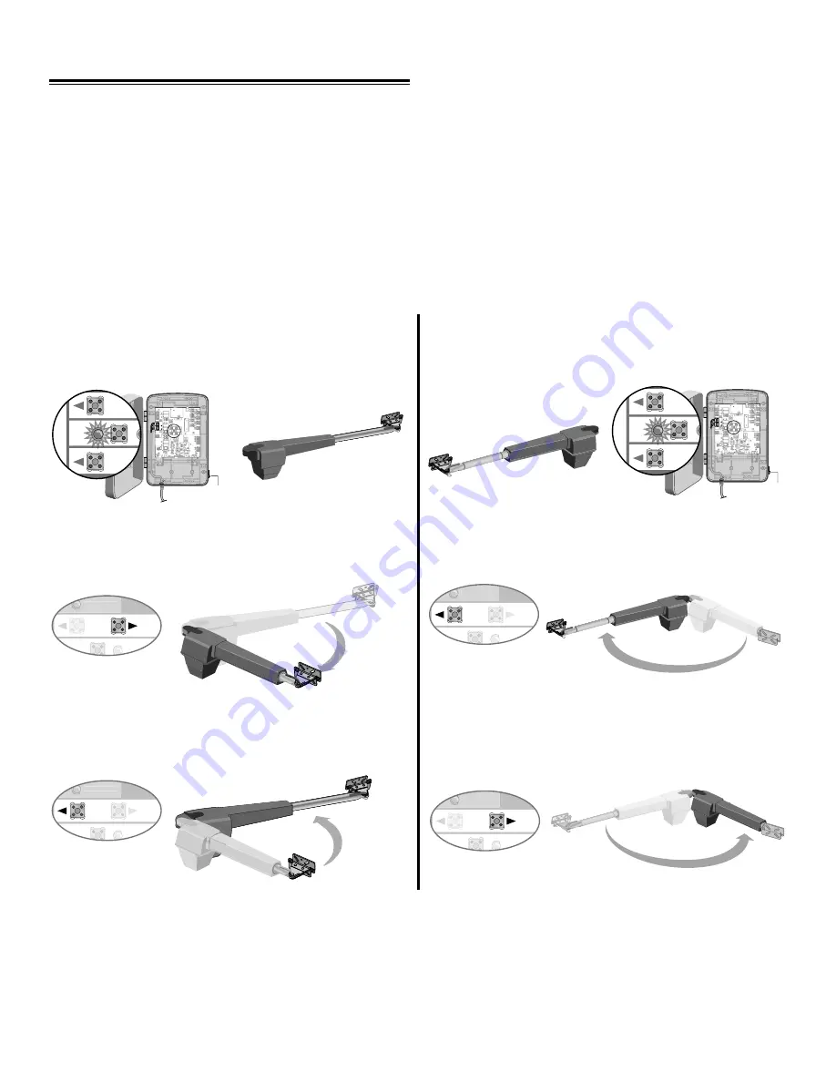
Test the limits by pressing the SBC to open and close the gate.

NOTE:

 If the SET OPEN LIMIT LED is still blinking, the limits were not programmed successfully. Repeat the 

programming making sure the gate is fully opened and closed for each respective limit. If the problem persists, refer to the 
Troubleshooting section.

PROGRAMMING

Program Limits

The limits are internal settings that indicate when the gates are in the fully open position and the fully closed position. For 
proper functionality, the limits must be learned during the installation process. The programmed limit process uses a 
combination of buttons on the control board. 

The specific buttons used for programming depends on which side of the gates the control box is mounted on and how 
many operators the installation includes. Refer to pages 11-12 to determine if the gate is Left- or Right-handed and for 
explanation of 

PULL-TO-OPEN

 and 

PUSH-TO-OPEN

.

If a mistake is made during the programming process press the 

RESET

 button on the outside of the control box to start 

over.

Single Arm Left-Hand Side 

Single Arm Right-Hand Side

NOTE:

 The “Learn Limits” mode can be exited at any time by pressing the 

RESET

 button. The mode will time-out 

automatically after 60 seconds of inactivity.

Z22 

R91 

CLOSE 
EDGE 

R94 

R92 

R93 

L1 

R1 

R2 

Z1 

K5 

K6 

K2 

F3 

10A 32V 

D1Ø 

OPEN EDGE/ 

OPEN EDGE/ 

PHO T O 

OPEN 
PHO T O 

CLOSE 
PHO T O 

R227 

R2Ø7 

Z2 Ø 

R223 

P1 

Z9 

Z8 

F2 

F6 

D4 

D2 

R9 

C64 

JMPR1 

R224 

U4 

CONTROL
INPUTS

FORCE 

TIMER TO 

CLOSE 

OFF MAX 

OPEN

SINGLE BUTTON

RESET

STOP

SHADOW 

INTERRUPT 

CHGR 
OVLD 

COM

COM

COM 

FUSE 
OPEN 

LOOP 
INPUTS 

POWER

BATT 1 

BATT 2 

F1  20A 32V 

R35 

D9 

Z3 

Z4 

U3 

D1 

F5 

C11 

C13 

C12 

D15 

C2 

R4 

R1Ø1 

R1ØØ 

R9Ø 

Q9 

K1 

R196 

Q22 

D8 

K3 

K4 

D21 

D22 

C4 

ACCESSORY 

OVLD 

D6 

JMPR2 

MOV1 

MOV2 

DB1 

U2 

Z12 

24 VAC/ 
SOLAR 
INPUT 

GATE 2 

ACCESSORY 

POWER 

MAGLOCK 

ALARM 

GATE 1

NC 

NO 

NO 

GRN

WHT

YEL

BLU

RED

BRN

GRN 

WHT 

YEL 

BLU 

RED 

BRN 

F4 

10A 32V 

F7 

24V 

COM
OVLD

TIMER 
RUNNING 

GATE 2 

SET 
OPEN 
LIMIT 

SET 
CLOSE 
LIMIT 

LEARN 
LIMITS 

DIAGNOSTIC 

GATE 1 

J4 

LEARN 
XMITTER 

MAGLOCK 

ON OFF 

L1 

D4 

D2 

R9 

C64 

JMPR1 

U4 

FORCE 

R35 

D9 

Z3 

Z4 

U3 

D1 

D27 

D27 

C11 

C12 

D6 

JMPR2 

MOV1 

DB1 

U2 

GATE 2 

SET 
CLOSE 
LIMIT 

LEARN 
LIMITS 

DIAGNOSTIC 

GATE 1 

MAGLOCK 

ON OFF 

SET

OPEN

LIMIT

LEARN LIMITS

 button

Programming 32

Press the 

GATE 1

 right button to move gate to the desired 

OPEN position. When gate is in the desired position, press 
the 

LEARN LIMITS

 button again. Control board will beep.

OPEN EDGE/ 

D27 

SET

CLOSE

DIAGNOSTIC

GATE 1

Press the 

GATE 1

 left button to move gate to the desired 

CLOSED position. When gate is in the desired closed 
position, press the 

LEARN LIMITS

 button again.

OPEN EDGE/ 

D27 

SET

CLOSE

DIAGNOSTIC

GATE 1

OPEN EDGE/ 

D27 

ACCESSORY 

OVLD 

Press the 

GATE 1

 left button to move gate to the desired 

OPEN position. When gate is in the desired position, press 
the 

LEARN LIMITS

 button again. Control board will beep.

OPEN EDGE/ 

D27 

ACCESSORY 

OVLD 

SET

CLOSE

DIAGNOSTIC

GATE 1

When the 

SET CLOSE LIMIT 

LED blinks, press the 

GATE 1

 right button. When gate is in the desired closed 

position, press the 

LEARN LIMITS

 button.

OPEN EDGE/ 

D27 

ACCESSORY 

OVLD 

SET

CLOSE

DIAGNOSTIC

GATE 1

The control board beeps and the 

SET OPEN LIMIT

 and 

SET CLOSE LIMIT 

LEDs stop blinking, 

programming is now complete.

Z22 

R91 

CLOSE 
EDGE 

R94 

R92 

R93 

L1 

R1 

R2 

Z1 

K5 

K6 

K2 

F3 

10A 32V 

D1Ø 

OPEN EDGE/ 

OPEN EDGE/ 

PHO T O 

OPEN 
PHO T O 

CLOSE 
PHO T O 

R227 

R2Ø7 

Z2 Ø 

R223 

P1 

Z9 

Z8 

F2 

F6 

D4 

D2 

R9 

C64 

JMPR1 

R224 

U4 

CONTROL
INPUTS

FORCE 

TIMER TO 

CLOSE 

OFF MAX 

OPEN

SINGLE BUTTON

RESET

STOP

SHADOW 

INTERRUPT 

CHGR 
OVLD 

COM

COM

COM 

FUSE 
OPEN 

LOOP 
INPUTS 

POWER

BATT 1 

BATT 2 

F1  20A 32V 

R35 

D9 

Z3 

Z4 

U3 

D1 

F5 

C11 

C13 

C12 

D15 

C2 

R4 

R1Ø1 

R1ØØ 

R9Ø 

Q9 

K1 

R196 

Q22 

D8 

K3 

K4 

D21 

D22 

C4 

ACCESSORY 

OVLD 

D6 

JMPR2 

MOV1 

MOV2 

DB1 

U2 

Z12 

24 VAC/ 
SOLAR 
INPUT 

GATE 2 

ACCESSORY 

POWER 

MAGLOCK 

ALARM 

GATE 1

NC 

NO 

NO 

GRN

WHT

YEL

BLU

RED

BRN

GRN 

WHT 

YEL 

BLU 

RED 

BRN 

F4 

10A 32V 

F7 

24V 

COM
OVLD

TIMER 
RUNNING 

GATE 2 

SET 
OPEN 
LIMIT 

SET 
CLOSE 
LIMIT 

LEARN 
LIMITS 

DIAGNOSTIC 

GATE 1 

J4 

LEARN 
XMITTER 

MAGLOCK 

ON OFF 

L1 

D4 

D2 

R9 

C64 

JMPR1 

U4 

FORCE 

R35 

D9 

Z3 

Z4 

U3 

D1 

D27 

D27 

C11 

C12 

D6 

JMPR2 

MOV1 

DB1 

U2 

GATE 2 

SET 
CLOSE 
LIMIT 

LEARN 
LIMITS 

DIAGNOSTIC 

GATE 1 

MAGLOCK 

ON OFF 

SET

OPEN

LIMIT

With the gate in the 

closed

 position, press the 

LEARN 

LIMITS

 button (

SET OPEN LIMIT

 LED will blink).

 Program  Open

 Program  Close

LEARN LIMITS

 button

With the gate in the 

closed

 position, press the 

LEARN 

LIMITS

 button (

SET OPEN LIMIT

 LED will blink).

 Program  Open

Program Close

RESET

BUTTON

RESET

BUTTON

Summary of Contents for GA400D

Page 1: ...ch Avenue Elmhurst Illinois 60126 1196 www chamberlain com Owner s Manual Please read this manual and the enclosed safety materials carefully Periodic checks of the operator are required to ensure safe operation The model number label is located inside the control box of your operator Serial Installation Date ...

Page 2: ...TION CAUTION WARNING WARNING 2 7 INTRODUCTION 2 Safety Symbol and Signal Word Review 3 Operator Specifications 4 5 Safety Installation Information 6 Carton Inventory 6 Hardware Inventory 7 Additional Items for Purchase 7 Tools Needed 8 12 PREPARATION AND OVERVIEW 8 Single Gate Overview 9 Dual Gate Overview 10 Check Your Gate 11 Gate Travel 12 Mounting Options 13 22 INSTALLATION 13 20 Attach Operat...

Page 3: ...NOTE Increased accessory power drawn from the operator will shorten the battery life Power Consumption 30 Watts max during battery charging Battery Charger Supply 14 5Vac nominal 30 VA max Maximum Gate Length 18 ft at 350 lbs Maximum Gate Weight 850 lbs at 6 ft Travel Time 20 seconds typical Temperature 20ºC to 50ºC 4ºF to 122ºF Contact Technical Support for applications below 20ºC Protection Fuse...

Page 4: ... pedestrian access shall be located such that persons will not come in contact with the moving vehicular gate 8 Pedestrians should never cross the pathway of a moving gate The gate operator is not acceptable for use on any pedestrian gate Pedestrians must be supplied with a separate pedestrian access 9 For an installation utilizing non contact sensors safety sensors see product manual on the place...

Page 5: ...g on or ride the gate during the entire travel of the gate 13 Each gate operator is provided with two safety warning placards The placards are to be installed on the front and back of the gate where they are plainly visible The placards may be mounted using cable ties through the four holes provided on each placard All warning signs and placards must be installed where visible in the area of the g...

Page 6: ...sion Bracket Model GA400D 1 Model GA420D 2 Control Box 1 with 1 Battery GA400D 2 Batteries GA420D Gate Operator Model GA400D 1 Model GA420D 2 Watertight Connector Model GA420D ONLY Extension Cable Model GA420D ONLY Arm End Cap Model GA400D 1 Model GA420D 2 Gate Bracket Model GA400D 1 Model GA420D 2 Post Bracket Model GA400D 1 Model GA420D 2 Plug In Transformer 1 Cable Ties 4 Warning Signs 2 Instal...

Page 7: ...UTOMATIC GATE LOCK AND HARD STOPS OPTIONAL In windy areas to ensure the gate stops at the same place each time we recommended the purchase of an automatic gate lock for the closed position and hard stop s for the open position GA420D Only JUNCTION BOX The Junction Box is needed to connect the second arm to the extension cable GA420D Installation Only UL Listed outdoor all weather junction box with...

Page 8: ...he opening or closing direction Exercise care to reduce the risk of nuisance tripping such as when a vehicle trips the sensor while the gate is still moving PVC conduit not provided to protect the power cable and low voltage wire from lawn mowers and string trimmers PVC conduit not provided to protect the power cable and low voltage wire from lawn mowers and string trimmers PREPARATION AND OVERVIE...

Page 9: ...only Ped estr ians mus t use sep arat e entr anc e Direction of Gate 1 Travel Direction of Gate 2 Travel Gate Operator Gate 1 Operator Cable Control Box with Batteries Antenna Warning Sign PVC conduit not provided to protect the power cable and low voltage wire from lawn mowers and string trimmers Gate Bracket Post Bracket Hinge Gate Operator Gate 2 Junction Box Extension Cable PVC conduit not pro...

Page 10: ...MUST swing freely and be supported entirely by its hinges Remove ANY ALL wheels from the bottom of gate Gate MUST NOT hit or drag across ground Gate MUST be level Gate and gate post MUST be plumb Preparation and Overview 10 ...

Page 11: ...y I n s i d e P r o p e r t y Outside Property Outside Property D i r e c t i o n o f G a t e T r a v e l Direction of Gate Travel Gate opens into the property Bracket for Pull To Open installation is provided Gate opens away from the property and will require the Push to Open kit 919GA Refer to the Push To Open kit for instructions ...

Page 12: ... top of operator must be mounted at least 10 up from ground Environmental conditions should be considered at this time In windy areas to ensure the gate stops at the same place each time we recommended the purchase of an automatic gate lock for the closed position and hard stop s for the open position Not recommended for plastic or vinyl gates Refer to gate manufacturer for recommendation and opti...

Page 13: ...e illustrations below show common gate hinges There are many styles of hinges available Gate Post Gate Post Gate Post J Bolt Hinge Point J Bolt Hinge Point Butt Hinge Point Barrel Hinge Point J Bolt Hinge Barrel Hinge Butt Hinge Top View Butt Hinge Point Gate Post Gate Post 1 ...

Page 14: ...Bracket Mounting Left Side Bracket Mounting Place the template provided on the back page under the gate hinge point Use a screwdriver or dowel rod to temporarily mark the location in front of the gate post Place the measuring tape under the gate hinge point and measure 5 3 4 Use a screwdriver or dowel rod to temporarily mark the location of the first measurement Right Side Bracket Mounting Right S...

Page 15: ...AS POSSIBLE above the marker Assemble post bracket by placing the extension bracket on top of post bracket Insert bolt through brackets and fasten with flange nut DO NOT TIGHTEN AT THIS TIME 3 Left Hand Gate Right Hand Gate 3 8 Ribbed Neck Bolt Extension Bracket Extension Bracket Post Bracket Post Bracket Flange Nut Flange Nut 3 8 Ribbed Neck Bolt ...

Page 16: ...on NOTE Turn operator over to remove screws Installation 16 4 5Determine Maximum Piston Travel To ensure proper operation it is essential to keep the piston from extending and retracting completely Manually extend piston out as far as possible push back 1 4 64 cm and then mark Always stay within these two marks to prevent the piston from bottoming out which could damage the transmission 1 2 3 Pist...

Page 17: ...ate Attach Brackets to Gate Operator Attach post bracket to gate operator using hex head shoulder bolt and lock nut with nylon insert Attach gate bracket to operator using release pin and hairpin clip 6 7 Post Bracket Hex Head Shoulder Bolt Lock Nut with Nylon Insert Release Pin Gate Bracket Hairpin Clip Piston Range After adjustments have been made make sure the piston is still within marked rang...

Page 18: ...tween the post bracket and operator Adjust gate bracket if the piston marks are not visible in both the open and close direction Tighten both bolts after final adjustments are made Bolts should be fully seated into the brackets NOTE If gate does not open and close completely adjust the position of the gate bracket Minimum of 1 4 Installation 18 8 Gate Travel Path G a t e T r a v e l P a t h ...

Page 19: ...E The gate bracket can be secured to the gate using a welder optional Lock Washers Flat Washers Hex Nuts Carriage Bolts 9 10 Lock Down Bolt 1 4 20 Welder Optional Hex Nut Flat Washer Lock Washer Gate Bracket 5 16 18 U Bolt NOTE For mounting on flat surfaces use 5 16 18 Hex Bolts 4 through slots instead of U Bolts Secure Post Bracket to Gate Post Mark holes for the post bracket Remove the clamp and...

Page 20: ...cable ties To prevent SERIOUS INJURY or DEATH from a moving gate Install warning signs on the front and back of the gate in PLAIN VIEW Permanently secure each warning sign in a suitable manner using fastening holes ATTENTION AVERTISSEMENT WARNING WARNING CAUTION For Model GA420D Only Repeat Steps 1 12 for second operator 11 12 13 14 Arm Motor Screws Arm Cover Reattach Motor Assembly Slide motor as...

Page 21: ... C2 C2 Q9 Q9 R9 R9Ø F8 F8 C73 C73 C72 C72 C71 C71 C7 C7Ø R42 R42Ø R423 R423 J24 J23 3 J24 J23 3ØA 32V A 32V 3 3ØA 32V A 32V J21 J21 30 30 30 30 C64 C64 R22 R22 U2 U2 K6 K6 JU1 JU1 JU2 JU2 DB1 DB1 Screws Screws Screws Control Board Reset Button Connections Coaxial Connector Alarm 18 L1 K2 Z22 F2 MOV1 D1 CHGR OVLD D129 Z4 D2 C11 C13 D16 F9 K1 F3 K3 K4 F1 Z12 GATE 2 GR WH YL BL RD BR GR WH YL BL RD B...

Page 22: ...E 1 LEARN LEARN XMITTER XMITTER LOCK LOCK ON ON OFF OFF C69 C69 PWR PWR AC PWR AC PWR SOLAR SOLAR R329 R329 R27 R27 MOV2 MOV2 R4 R4 C2 C2 BIPART DELAY BIPART DELAY LOCK Q9 Q9 R9 R9Ø F8 F8 C73 C73 C72 C72 C71 C71 C7 C7Ø R42 R42Ø R423 R423 J24 J23 3 J24 J23 3ØA 32V A 32V 3 3ØA 32V A 32V J21 J21 30 30 30 30 C64 C64 R22 R22 U2 U2 K6 K6 JU1 JU1 JU1 JU1 JU2 JU2 DB1 DB1 R184 R184 ALARM 18 18 K2 K2 Z22 Z2...

Page 23: ...32V 3 3ØA 32V A 32V J21 J21 30 30 30 30 C64 C64 R22 R22 U2 U2 J18 J18 K6 K6 JU1 JU1 JU2 JU2 DB1 DB1 D36 D36 23 Wiring Insert Operator Cable Insert watertight connector into the bottom of the control box and tighten with nut Insert operator cable through watertight connector mounted in the bottom of the control box To reduce the risk of SEVERE INJURY or DEATH ANY maintenance to the operator or in t...

Page 24: ...SHADOW INTERRUPT CHGR OVLD COM COM COM FUSE OPEN LOOP INPUTS POWER BATT 1 BATT 2 F1 20A 32V R35 D9 Z3 Z4 U3 D1 D27 F5 C11 C13 C12 D15 C2 R4 R1Ø1 R1ØØ R9Ø Q9 K1 R196 Q22 D8 K3 K4 D21 D22 C4 ACCESSORY OVLD D6 JMPR2 MOV1 MOV2 DB1 U2 Z12 24 VAC SOLAR INPUT GATE 2 ACCESSORY POWER MAGLOCK ALARM GATE 1 C C NC NO NO GRN WHT YEL BLU RED BRN GRN WHT YEL BLU RED BRN F4 10A 32V F7 24V COM OVLD TIMER RUNNING G...

Page 25: ...IMITS GATE 1 GATE 1 C69 C69 J2 J2Ø D8 D8 D4 D4 R9 R9 R329 R329 R27 R27 MOV2 MOV2 R4 R4 C2 C2 Z1 Z1 R2 R2 K5 K5 F12 F12 Q9 Q9 R9 R9Ø F8 F8 Q6 Q6 Q1 Q1 C75 C75 C73 C73 C72 C72 C71 C71 C7 C7Ø C66 C66 C65 C65 C68 C68 C33 C33 F11 F11 R42 R42Ø R423 R423 J24 J23 3 J24 J23 3ØA 32V A 32V 3 3ØA 32V A 32V J21 J21 30 30 30 30 C64 C64 R22 R22 U2 U2 J18 J18 K6 K6 JU1 JU1 JU2 JU2 DB1 DB1 D36 D36 C71 C7Ø ON OFF L...

Page 26: ...1 R2 Z1 K5 K6 K2 F3 10A 32V D1Ø OPEN EDGE PHOTO OPEN PHOTO CLOSE PHOTO R227 R2Ø7 Z2Ø R223 P1 Z9 Z8 F2 F6 D4 D2 R9 C64 JMPR1 R224 U4 CONTROL INPUTS FORCE TIMER TO CLOSE OFF MAX OPEN SINGLE BUTTON RESET STOP SHADOW INTERRUPT CHGR OVLD COM COM COM FUSE OPEN LOOP INPUTS POWER BATT 1 BATT 2 F1 20A 32V R35 D9 Z3 Z4 U3 D1 D27 F5 C11 C13 C12 D15 C2 R4 R1Ø1 R1ØØ R9Ø Q9 K1 R196 Q22 D8 K3 K4 D21 D22 C4 ACCES...

Page 27: ...te Can Cau se Inju ry or De ath KEE P CLEA R Gate may mov e at any time witho ut prior warn ing Do not let child ren oper ate the gate or play in the gate area This entra nce is for vehic les only Pede stria ns mus t use sepa rate entra nce Screws 4 Junction Box not provided Junction Box Cover Within 5 Control Box Gate Operator Gate 2 Gate Operator Gate 1 Junction Box Extension Cable Within 5 PVC ...

Page 28: ... Insert cables and watertight connectors into the holes in the bottom of the junction box not provided Feed extension cable through PVC conduit and secure with connector nut Screws 4 Junction Box not provided Junction Box not provided PVC Conduit Operator Cable Watertight Connector Nut Watertight Connector Nut Watertight Connector Watertight Connector Extension Cable Junction Box PVC Conduit Opera...

Page 29: ...ng Run wires through PVC conduit to protect the power wires from lawn mowers string trimmers etc NOTE Calculated using NEC guidelines Local codes and conditions must be reviewed for suitability of wire installation To AVOID damaging gas power or other underground utility lines contact underground utility locating companies BEFORE digging ATTENTION AVERTISSEMENT WARNING CAUTION CAUTION PRECAUCIÓN A...

Page 30: ...8 C68 C33 C33 F11 F11 R186 R186 R42 R42Ø R423 R423 J24 J23 3 J24 J23 3ØA 32V A 32V 3 3ØA 32V A 32V J21 J21 30 30 30 30 C64 C64 R22 R22 U2 U2 J18 J18 K6 K6 JU1 JU1 JU1 JU1 JU2 JU2 DB1 DB1 R184 R184 MOV1 MOV1 CHGR OVLD AC PWR SOLAR MOV2 R4 C2 JU1 LE BUTTON K2 K1 K1 SET OPEN LIMIT C73 C72 C71 DIAGNOSTIC OPEN SINGLE BUTTON RESET STOP CTRL PWR CTRL OVLD PWR WR Connect indoor Transformer to Control Boar...

Page 31: ... D44 C11 C11 C13 C13 C12 C12 D16 D16 F9 F9 R1 R1Ø1 R1 R1ØØ ØØ K1 K1 Q22 Q22 F3 F3 K3 K3 K4 K4 R196 R196 F1 F1 Z12 Z12 GATE 2 GATE 2 GATE 1 GATE 1 MAGR MAGR SOL SOL GR GR WH WH YL YL BL BL RD RD BR BR GR GR WH WH YL YL BL BL RD RD BR BR F7 F7 24V 24V CTRL CTRL OVLD OVLD TIMER TIMER RUNNING RUNNING GATE 2 GATE 2 SET SET OPEN OPEN LIMIT LIMIT SET SET CLOSE CLOSE LIMIT LIMIT LEARN LEARN LIMITS LIMITS ...

Page 32: ... LIMIT LEARN LIMITS DIAGNOSTIC GATE 1 MAGLOCK ON OFF SET OPEN LIMIT LEARN LIMITS button Programming 32 Press the GATE 1 right button to move gate to the desired OPEN position When gate is in the desired position press the LEARN LIMITS button again Control board will beep OPEN EDGE D27 SET CLOSE DIAGNOSTIC GATE 1 Press the GATE 1 left button to move gate to the desired CLOSED position When gate is ...

Page 33: ... board beeps and the SET OPEN LIMIT and SET CLOSE LIMIT LEDs stop blinking programming is now complete Test the limits by pressing the SBC to open and close the gate NOTE If the SET OPEN LIMIT LED is still blinking the limits were not programmed successfully Repeat the programming making sure the gate is fully opened and closed for each respective limit If the problem persists refer to the Trouble...

Page 34: ...Control SBC button on the control board open and then close the gate If the gate stops and or reverses before reaching the fully open or closed position increase the force by turning the force control slightly Run operator through a complete cycle NOTE Weather conditions can affect the gate movement so seasonal adjustment may be required The force control is factory set to the mid position Timer t...

Page 35: ...E USE Operation is subject to the following two conditions 1 this device may not cause harmful interference and 2 this device must accept any interference received including interference that may cause undesired operation To Add a Wireless Keyless Entry not provided 1 Press LEARN XMITTER button and release LED will light up 2 Enter a four digit personal identification number PIN of your choice on ...

Page 36: ...st fully open for the timer feature to be active and close the gate s Any radio command or pressing the single button on the control board prior to the TCC time expiring will close the gate The TTC is reset by any signals from the loops close edges and close safety sensors IR s Party mode If the Timer to Close feature is enabled and you would like the gate to remain open simply push the reset butt...

Page 37: ...ce Inspect for wear or damage Entrapment Protection Systems Manual Release Gate Accessories Electrical Mounting Hardware Batteries Total Unit CHECK AT LEAST ONCE EVERY NOTES 1 Disconnect power before servicing 2 Severe or high cycle usage will require more frequent maintenance checks 3 Inspection and service should always be performed anytime a malfunction is observed or suspected 4 When servicing...

Page 38: ... OFF PWR C69 OFF MAX J2Ø PWR SINGLE BUTTON AC PWR SOLAR D8 D4 R9 R329 R27 MOV2 R4 C2 BIPART DELAY LOCK GND Z1 R1 R2 K5 F12 Q9 R9Ø F8 Q6 Q1 J19 ACCESSORY 0VLD R182 C1Ø1 C75 C73 C72 C71 C7Ø C66 C65 C68 C33 F11 R186 R42Ø R423 J24 J23 3ØA 32V 3ØA 32V J21 2Ø 30 C64 R22 U2 J18 K6 JU1 JU2 DB1 D36 R184 16 19 17 18 13 optional Fault Alarm Automatic Gate Lock WHT GRN BRN YEL BLU RED WHT GRN BRN YEL BLU RED ...

Page 39: ...on and press the GATE 1 buttons to move the arm If the arm does not move continuously disconnect arm from Gate 1 and connect the arm to the Gate 2 connector and repeat the attempt to move the arm If the arm does not move continuously on either Gate 1 or 2 replace the arm Gate 1 has encountered an obstruction Make sure the path of the gate is clear and the gate moves freely If there is no obstructi...

Page 40: ...on Press the RESET button and verify that the Safety LEDs OPEN EDGE and CLOSE EDGE PHOTO are OFF If either is ON clear any obstructions and verify the LED turns off NOTE The RESET button may need to be hit multiple times since the LEDs turn off after 10 seconds when the unit goes to sleep Optional Accessory Interrupt loop or Shadow loop is obstructed Press the RESET button and verify that the INTE...

Page 41: ...fter 10 seconds Verify the wire connects between STOP and CTRL PWR terminals Single Button Control SBC button connection loose Check wiring for SBC button Use the on board single button to verify operator will respond Bad control board Call technical support for help with replacement parts Unit does not respond to Battery not connected At least one charged battery must be connected for the unit re...

Page 42: ...erify that the TIMER RUNNING LED is flashing Alarm constantly sounds Double entrapment occurred Two successive obstructions were encountered while for 5 minutes Sounds moving the gate Press the RESET button and ensure that the gate path is clear of whenever a command is all obstructions Check the FORCE setting to make sure it is properly set issued Alarm is beeping 3 times on Low battery Measure t...

Page 43: ...4392 Antenna 1 4 922GA Battery with Harness 1 5 K204B0195 Indoor Transformer 1 6 K29 20095 Alarm 1 Not Shown K74 33975 Complete Control Box without battery 1 K1A5747 Receiver Module 315MHz 1 K1A5747 2 Receiver Module 390MHz optional 1 Repair Parts Control Box NOTE The fuse is a standard 20 Amp fuse that is available from your local automotive store ...

Page 44: ... Assembly Includes Arm Motor and Plastic Cover 1 Not Shown K DBL 0095SA Hardware Kit Includes One Extension Bracket One Gate Bracket One Post Bracket and One Hardware Bag 1 01 33859 Owner s Manual 1 01 33859SP Owner s Manual Spanish 1 K 41ADBL 1011SA Screws for housing pack of 4 Repair Parts Gate Operator Arm ...

Page 45: ... manual To order call 1 866 826 4943 or visit our website www chamberlain diy com 916GA Gate Arm Pin Lock The pin lock kit is designed to prevent disconnection of the gate operator and the gate while providing a means to open the gate in case of power failure 914GA Low Voltage Wire 100 Low voltage wire is required to connect the transformer to the control box Also can be used to connect optional s...

Page 46: ...ry rebuilt parts at Seller s sole option ALL IMPLIED WARRANTIES FOR THE PRODUCT INCLUDING BUT NOT LIMITED TO ANY IMPLIED WARRANTIES OF MERCHANTABILITY AND FITNESS FOR A PARTICULAR PURPOSE ARE LIMITED IN DURATION TO THE ONE YEAR LIMITED WARRANTY PERIOD SET FORTH ABOVE AND NO IMPLIED WARRANTIES WILL EXIST OR APPLY AFTER SUCH PERIOD Some States do not allow limitations on how long an implied warranty...

Page 47: ...NOTES 47 Notes ...

Page 48: ... 2009 The Chamberlain Group Inc 01 33859D All Rights Reserved TEMPLATE FOR POST BRACKET MOUNTING 1 3 2 4 5 1 3 2 4 5 5 3 4 53 4 ...

Reviews: