20
P R O G R A M M I N G
MAINTENANCE ALERT SYSTEM (MAS)
Feature:
An internal cycle counter will activate a flashing LED on
the 3-button control station when the preset number of cycles or
months has elapsed (whichever occurs first). Setting this feature
is optional. By default this feature will never activate. Logic 3.0
operators incorporate a self diagnostic feature built into the MAS
LED. In addition to indicating when routine maintenance is due,
the MAS LED can be used to troubleshoot some problems with
the operator.
Benefit:
The Maintenance Alert System (MAS) assists the
installing dealer in setting up a routine maintenance program.
Once programmed, the MAS notifies the end user (with a flashing
LED on the 3-button station) when a preset number of
cycles/months has elapsed and scheduled maintenance is due.
To Program:
1. The Maintenance Alert System (MAS) assists the installing
dealer in setting up a routine maintenance program. Once
programmed, the MAS notifies the end user (with a flashing
LED on the 3-button station) when a preset number of
cycles/months has elapsed and scheduled maintenance is due.
2. Close the door.
3. Turn the selector dial to PROGRAM.
4. Press and release the MAS SET button.
5. Press the STOP button once to clear the MAS counter.
6. Press the OPEN button once for every 5,000 cycles
increments. Press the CLOSE button once for every 3 month
increments. Press the STOP button once to clear the MAS
memory.
7. Press the MAS SET button to complete the programming. The
on board LED will flash back the programmed settings. The
OPEN LED will flash once for every 5,000 cycles. The CLOSE
LED will flash once for every 3 months.
8. Turn the selector dial back to the desired wiring type.
NOTE:
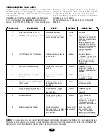
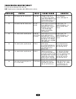
If MAS LED flashes 2 or more flashes in a row followed by
a pause, an operator error occurred. Turn to page 28 to diagnose
problem.
Example:
A door is installed with 30,000 cycle springs and has
an annual service contract. To set the MAS, turn selector dial to
PROGRAM, press MAS button, press the STOP button to clear
the memory and then press the OPEN button 6 times (30,000
cycles) and close 4 times (12 months). Press the MAS again to
complete the programming. Set the selector dial to desired
wiring type.
Special Notes about MAS:
A 5th wire must be run to the control
station to activate the MAS LED. The MAS LED on the logic board
is always enabled. When the operator is serviced after the MAS
LED has started to flash, repeat the setup procedure to program
in the number or cycles desired until the next service visit OR
press and hold the MAS button for 5 seconds in the PROGRAM
mode to reset the MAS with its current programmed value. To
disable the MAS, follow the programming procedure above and
press the STOP button to reset the counter to zero. Every time
the operator leaves the close limit is counted as one cycle.
To view how many cycles are programmed into the MAS, set the
Operation will vary
depending on
wiring type
SELECTOR DIAL
OPEN
CLOSE
STOP
Adds 5,000 cycles to Maintenance Alert System
Activation Counter.
Adds 3 Months to Maintenance Alert System
Activation Timer.
Clears memory, sets Maintenance Alert System
Activation Counter to 0 cycles and 0 months.
Press This To Get This
3-BUTTON STATION
OPEN
CLOSE
STOP
Maintenance
Alert LED
selector dial to DIAGNOSTIC and press the MAS button. The
OPEN button LED will flash once for every 5,000 cycle increment
programmed and the CLOSE button LED will flash once for every
3 month increment programmed.
To view how many cycles have elapsed since the last time the
MAS was programmed, set the selector dial to “Diagnostic” and
press the “MAS” button. Press the OPEN button; the OPEN LED
will flash once for every 5,000 cycles that has elapsed. Press the
CLOSE button; the CLOSE LED will flash once for every (3)
months that has elapsed. Press the MAS button to exit.
Summary of Contents for H
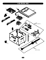
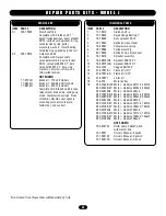
Page 30: ...30 E L E C T R I C A L B O X 1 4 7 6 10 5 2 11 K2 K1 3 9 8 K72 12515 1 K72 14130 1 ...
Page 32: ...32 M O D E L J 12 14 16 15 13 3 8 10 2 9 11 2 1 4 3 7 5 6 6 K1 K2 K72 19975 K72 19974 ...
Page 34: ...34 M O D E L H 19 15 14 11 2 16 17 18 10 9 4 3 1 12 7 7 13 5 6 2 8 K1 K2 K72 19974 K72 19979 ...
Page 38: ...38 O P E R A T O R N O T E S ...
Page 39: ...39 O P E R A T O R N O T E S ...


