background image

1

INTRODUCTION

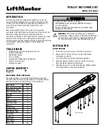
The following procedure replaces the LA500 arm trolley nut, 
should it become damaged by a car strike to the gate or other 
similar event. This procedure is intended to be performed in a 
clean shop by personnel confident in performing such 
procedures.

Most of the LA500’s internal drive train parts are factory 
assembled under tight tolerances. Should any of these parts lose 
alignment, reliable performance will be impacted. This 
procedure’s performance may impact the arm warranty coverage; 
therefore, if the subject arm is still covered under product 
warranty, please consider replacing the arm instead of performing 
this procedure. Retain all hardware; it will be needed for 
reassembly.

To reduce the risk of INJURY or DEATH:
•   DISCONNECT power and battery BEFORE installing or 

servicing operator.

•   See manual regarding maintenance and required safety 

testing prior to servicing.

TROLLEY NUT SERVICE KIT

MODEL K75-39337

TOOLS NEEDED

• 

LA500 control box with photoelectric sensors

• Torque 

screwdrivers

• Metric 

Allen 

wrench

• 12V, 

7A 

battery

• 

Flathead and Phillips head screwdrivers

• 

Fastener (E-ring) pliers

• Needle 

nose 

pliers

CARTON INVENTORY

 Description 

QTY 

Trolley nut 

1

ADDITIONAL PARTS INCLUDED

The following items are provided for additional damage that 
occurred when the trolley nut was broken, or for parts that may 
have become lost in the performance of this procedure. 

Description

QTY

Pan Head Screw, M5

2

Split Washer, M6

3

Pan Head Screw, M6

1

Nut, M6

3

O-ring

1

Pin

1

Retaining Ring

1

Retaining Ring

1

Bearing

1

Trolley Plate

2

Bushing Retainer

1

Flat Washer, M6

2

Screw M6

2

Trolley Pin

1

Base plate

1

Arm Gasket

1

Screw, M5

12

WARNING:

 This product can expose you to chemicals 

including lead, which are known to the State of California to 
cause cancer or birth defects or other reproductive harm. 
For more information go to 

www.P65Warnings.ca.gov.

INSTALLATION

OPEN THE ARM

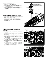
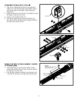
1.  Invert the arm to gain access to the top cover screws.
2.  Remove the 12 top cover screws using a T25 torque 

screwdriver or wrench.

3.  Turn the arm back to normal operating orientation.
4.  Carefully separate the top cover from the rest of the arm. 

Note that the post bracket might fall out.

5.  Place the top cover in a safe, clean location. Make sure that 

the arm gasket does not get contaminated.

Post Bracket

Top Cover

Top Cover Screws

Summary of Contents for K75-39337

Page 1: ...Phillips head screwdrivers Fastener E ring pliers Needle nose pliers CARTON INVENTORY Description QTY Trolley nut 1 ADDITIONAL PARTS INCLUDED The following items are provided for additional damage tha...

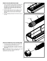
Page 2: ...sembly to gain access to the free ends of the retaining ring 3 Using a set of fastener E ring pliers slide the retaining ring towards the motor to gain access to the trolley pin that it secures into p...

Page 3: ...rain flange screws Removing these parts will require that the arm be entirely replaced REMOVE THE BUSHING RETAINER FROM THE ARM NOSE 1 Using a wide flathead screwdriver or T25 torque wrench remove the...

Page 4: ...PLATE 1 Gain access to the bottom of the arm 2 Using the appropriate wrenches remove the two nuts from the bolts that secure the base plate to the two trolley plates 3 Note the order of the flat and s...

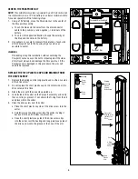
Page 5: ...the drive screw from the collar at the Passpoint assembly 3 Remove the bearing and end caps from the drive screw and set aside Drive Screw Long Plastic Cap REPLACE THE BROKEN TROLLEY NUT ON DRIVE SCRE...

Page 6: ...Plastic Cap on Drive Screw Short Plastic Cap Trolley Nut Collar located at the center of the Drive Screw Bearing Long Plastic Cap Drive Screw CENTER THE PASSPOINT NUT NOTE This LA500 arm system is po...

Page 7: ...ure that the trolley nut is placed in the center of the drive screw 1 Use a tape measure to make sure the trolley nut is located center on the drive screw 2 To reassemble the travel assembly over the...

Page 8: ...rrounding the trolley nut ensuring that the guide for the brackets meet up with the clear holes on the brackets that are designed to receive them 2 Tighten the 5 Allen screw to the top of the brackets...

Page 9: ...trolley pin back into the hole 3 Return the retaining ring to the retaining groove Make sure that the circumference of the retaining ring covers the trolley pin instead of the gap between the retainin...

Page 10: ...into the groove of the Passpoint nut 2 Secure the Passpoint assembly top bracket with the three Phillips head mounting screws and washers REPLACE THE LED CIRCUIT CARD 1 Inspect the bottom of the LED c...

Page 11: ...5 Is the retaining ring covering the trolley pin 6 Is the bushing retainer assembled ASSEMBLE THE TOP COVER 1 Inspect the washer around the motor housing looking for creases tears or folds Correct or...

Page 12: ...n c Using the move gate buttons move the travel assembly to the outer limit of the arm Press set close d Using the move gate buttons move the travel assembly to the inter limit of the arm Press set op...

Page 13: ...amom trique Cl Allen m trique Batterie de 12 V 7AH Tournevis t te plate et t te cruciforme Pinces de retenue anneau de type E Pinces bec effil CONTENU DE LA BO TE Description QT crou de chariot 1 PI C...

Page 14: ...oir acc s aux extr mit s libres de la bague de retenue 3 Avec un anneau en E glisser la bague de retenue vers le moteur pour avoir acc s la goupille du chariot qui le retient en place 4 Avec un petit...

Page 15: ...errer toute autre vis d accouplement de la transmission Le retrait de ces pi ces exigerrait de remplacer enti rement le bras ENLEVER LA FIXATION DE DOUILLE DU NEZ DU BRAS 1 Avec un tournevis t te plat...

Page 16: ...Acc der au bas du bras 2 Avec les cl s appropri es enlever les deux crous des boulons qui retiennent la plaque de base aux deux plaques du chariot 3 Noter l ordre dans lequel les rondelles plates et f...

Page 17: ...l assemblage du point de contr le 3 Enlever le roulement et les capuchons d extr mit de la vis d entra nement et les mettre de c t REMPLACER L CROU DE CHARIOT BRIS SUR LA VIS D ENTRA NEMENT 1 Si l cro...

Page 18: ...REMARQUE Le syst me de bras LA500 est aliment par un moteur de 24 V c c mais le moteur fonctionnera batterie 12 V c c une course et une vitesse plus lentes pour faciliter l ex cution des tapes suivant...

Page 19: ...que l crou du chariot est plac au centre de la vis d entra nement 1 Se servir d un ruban mesurer pour s assurer que l crou du chariot est plac au centre de la vis d entra nement 2 Pour r assembler l...

Page 20: ...entourant l crou de chariot et v rifier que le guide des supports s aligne sur les orifices des supports pr vus pour les recevoir 2 Serrer la vis Allen no 5 sur le dessus des supports afin de brider c...

Page 21: ...la goupille dans l orifice 3 Remettre la bague de retenue dans la rainure de retenue S assurer que la circonf rence de la bague de retenue couvre la goupille du chariot au lieu de l cart entre les ex...

Page 22: ...u de point de contr le 2 Fixer le support sup rieur de l assemblage de point de contr le avec les trois vis de montage t te cruciforme et les rondelles REMETTRE EN PLACE LA CARTE DE CIRCUIT IMPRIM DEL...

Page 23: ...bague de retenue couvre t elle la goupille du chariot 6 La fixation de douille est elle assembl e ASSEMBLER LE COUVERCLE SUP RIEUR 1 Inspecter la rondelle autour du bo tier du moteur en recherchant de...

Page 24: ...lacer l assemblage de course jusqu la limite ext rieure du bras Appuyer sur le bouton pour SET CLOSE r gler la fermeture d Avec les boutons de MOVE GATE d placement de la barri re d placer l assemblag...

Page 25: ...Phillips y planos Pinzas del sujetador retenedor Pinzas de punta CONTENIDO DE LA CAJA Descripci n CANT Tuerca del carro 1 PARTES ADICIONALES INCLUIDAS Los siguientes art culos se proporcionan para los...

Page 26: ...es del anillo de retenci n 3 Con un juego de pinzas del sujetador retenedor deslice el anillo de retenci n hacia el motor para acceder al pasador del carro que lo fija en su lugar 4 Con un destornilla...

Page 27: ...rida del tren de transmisi n El desmontaje de estas piezas requerir que el brazo se reemplace por completo RETIRAR EL RETENEDOR DEL COJINETE DE LA PUNTA DEL BRAZO 1 Con un desarmador plano ancho o una...

Page 28: ...LACA BASE 1 Obtenga acceso a la parte inferior del brazo 2 Con las llaves apropiadas retire las dos tuercas de los pernos que fijan la placa base a las dos placas del carro 3 Observe el orden de las r...

Page 29: ...f n desde el collar en el ensamblaje del punto de paso 3 Retire las placas de apoyo y las tapas de los extremos del tornillo sinf n y col quelas a un lado REEMPLAZAR LA TUERCA ROTA DEL CARRO EN EL TOR...

Page 30: ...LA500 est alimentado por un motor de 24 Vcc pero el motor funcionar con una bater a de 12 Vcc a un ritmo y velocidad m s lentos para facilitar el funcionamiento de los siguientes pasos 1 Con una bate...

Page 31: ...da en el centro del tornillo sinf n 1 Use una cinta m trica para asegurarse de que la tuerca del carro est ubicada en el centro del tornillo sinf n 2 Para volver a montar el ensamblaje de recorrido so...

Page 32: ...a tuerca del carro asegur ndose de que la gu a para las m nsulas coincida con los orificios transparentes de las m nsulas dise adas para recibirlas 2 Apriete el tornillo Allen nro 5 a la parte superio...

Page 33: ...el pasador del carro en el orificio 3 Vuelva a colocar el anillo de retenci n en la ranura de retenci n Aseg rese de que la circunferencia del anillo de retenci n cubra el pasador del carro en lugar d...

Page 34: ...erior del ensamblaje del punto de paso con los tres tornillos de montaje Phillips y las rondanas REEMPLAZAR LA TARJETA DE CIRCUITO LED 1 Inspeccione la parte inferior de la tarjeta de circuito LED y a...

Page 35: ...retenci n cubre el pasador del carro 6 Est ensamblado el retenedor del cojinete ENSAMBLAR LA CUBIERTA SUPERIOR 1 Inspeccione la rondana alrededor de la carcasa del motor buscando pliegues roturas o do...

Page 36: ...ando b Coloque el interruptor de cambio del port n en la posici n de brazo1 c Con los botones para MOVE GATE mover el port n mueva el ensamblaje de recorrido hasta el l mite exterior del brazo Presion...

Reviews: