
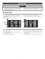
11
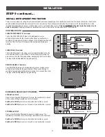
INSTALLATION
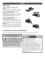
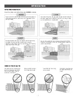
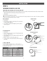
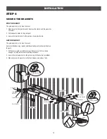
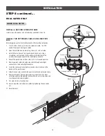
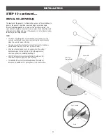
TEMPLATE METHOD
1. Close the gate.
2. Place the template (provided on the back page of this manual) under
the center of the gate hinge point.
3. Use a screwdriver or dowel rod to temporarily mark the location in
front of the gate post.
OR
TAPE MEASURE METHOD
1. Close the gate.
2. Place the measuring tape under the center of the gate hinge point and
measure out 7 inches (17.8 cm).
3. Use a screwdriver or dowel rod to temporarily mark the location of the
first measurement.
4. Measure 7 inches (17.8 cm) from the previous mark.
5. Use the screwdriver or dowel rod to mark the location of the second
measurement.
Gate Post
Gate
Gate Post
TOP VIEW
TOP VIEW
Gate Hinge Point
Gate Hinge Point
7" (17.8 cm)
7" (17.8 cm)
Gate
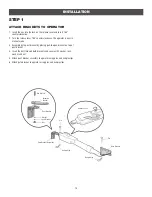
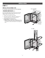
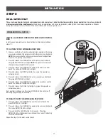
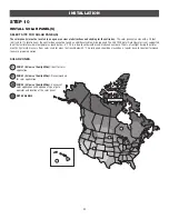
STEP 2
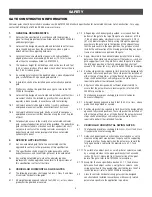
DETERMINE MOUNTING LOCATION
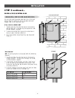
MEASURING AND MARKING FOR THE GATE BRACKET
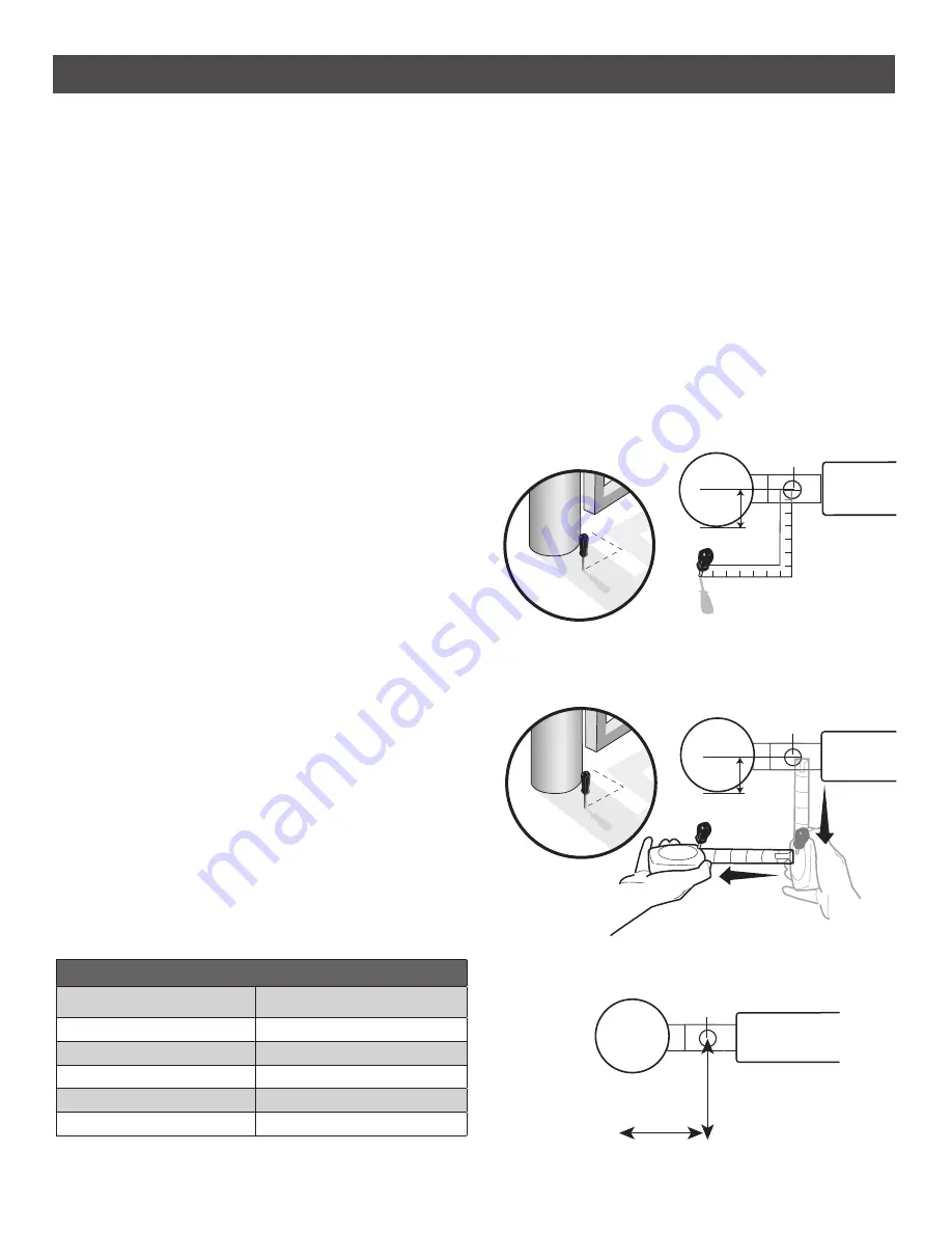
Before proceeding, begin with the gate in the fully closed position. There are two methods for determining the proper location of the post brackets:
• Paper template (Located on the back page of this manual. Must be cut out.)
• Tape
measure.
Either method will work depending on preference.
NOTE:
There should only be a maximum of 4" (10.2 cm) from the center of the hinge to the edge of the post or column. If the distance is greater than
4" (10.2 cm) entrapment protection for this area is required.
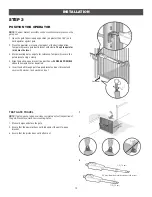
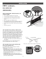
TEMPLATE METHOD
TAPE MEASURE METHOD
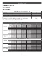
DIMENSION CHART
A
B
7" (17.8 cm)
7" (17.8 cm)
8" (20.3 cm)
6" (15.2 cm)
7-1/2" (19.1 cm)
7-1/2" (19.1 cm)
6-1/2" (16.5 cm)
6-1/2" (16.5 cm)
6" (15.2 cm)
6" (15.2 cm)
ALTERNATE DIMENSIONS
The ideal installation measurements are A = 7" (17.8 cm) and B = 7"
(17.8 cm). If different measurements are used, the sum of A and B cannot
be greater than 15" (38.1 cm).
ALTERNATE DIMENSIONS
(A)
(B)
Gate Post
Gate Hinge Point
Gate
4" (10.2 cm)
maximum
4" (10.2 cm)
maximum


