53
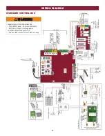
WIRING DIAGRAM
N.C.
SBC
OPN
CLS
STP
COM
EYE
ONL
Y
EYE/
EDGE
EYE/
EDGE
COM
1
2
3
OPEN
CLOSE
TO MAIN
BOARD
POWER
12V 7AH Batter
y
Black
Red
12V 7AH Batter
y
Attach to Metal Chassis
Maglock
(Optional)
(not provided)
Solenoid Lock
(Optional)
(not provided)
To J15
Accessor
y
Power
Outlets
Two 12V Solar Panels in Series
Black
Red
Blocking
Diode
Brown
Purple
Transformer 200 V
A
Bridge Rectifier
Wire Nut
Gray
Blue
Black
Red
Y
ellow
White
Red
Orange
N
GND
Input Power Connection
EMI FIL
TER/SURGE PROTECTION BOARD
L
Switch/5A Breaker
Transformer Run Kit
Black
Black
Red
White
Ground
Primar
y Operator
Secondar
y Operator
Black
Red
Transformer
(Optional)
Piezo Alarm
White
White
Purple
Reset Switch
Red
Black
Loop
Detector
Attach to Outlet
Metal Chassis
With a Single Screw
Attach to Outlet Metal Chassis
With a Single Screw
EXP
ANSION BOARD
Field Wiring
Wire Loop
Wire Loop
Wire Loop
Field Wiring
EDGE OR EYE
EDGE OR EYE
EYE
Field Wiring
Photoelectric Sensors
Edge
Edge
Photoelectric Sensors
Y
ellow
Blue Black
Red
Coaxial Antenna Cable
Antenna
STANDARD CONTROL BOX
To protect against fire and electrocution:
• DISCONNECT power (AC or solar and battery)
BEFORE installing or servicing operator.
For continued protection against fire:
• Replace ONLY with fuse of same type and rating.
Summary of Contents for Liftmaster Elite LA500
Page 2: ......


