background image

3-en

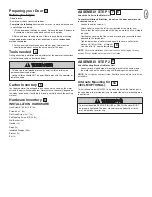
Preparing your Door 

Before you begin:

• Disable locks. 

• Remove any ropes connected to door. 

• 

Complete the following test 

to make sure your  door is balanced and

is not sticking or binding: 

1. Lift the door about halfway as shown. Release the door. If balanced,

it should stay in place, supported entirely by its springs.

2. Raise and lower the door to see if there is any binding or sticking. 

IF YOUR DOOR BINDS

STICKS OR IS OUT OF BALANCE

CALL A TRAINED DOOR

SYSTEMS TECHNICIAN

.

3. Verify equal cable tension on each side of door. Cable tension

should remain equal during the entire travel of the door.

Tools needed

During assembly, installation and adjustment of the operator, instructions
will call for hand tools as illustrated below.

3

4

• This device is not intended for use by small children or infirmed
persons without supervision.
• young children should NOT be permitted to play with the operator or
remote controls.

Carton Inventory

Your door operator is packaged in one carton which contains the motor
unit and the parts illustrated below. Note that accessories will depend on
the model purchased. If anything is missing, carefully check the packing
material.

Hardware Inventory

INSTALLATION HARDWARE

Hex Screw #14-10x1-7/8" (4x)

Screw #6x-1" (2x)

Flat Head Screw 8x1” (2x)

Self Tapping Screw #10-32 (2x)

Wall Anchor (4x)

Handle (1x)

Rope (1x)

Insulated Staples (20x)

Bracket (1x)

Bit (1x)

5

6

ASSEMBLY STEP 1

Attach the Collar to the Motor Unit

To avoid installation difficulties, do not run the door operator until
instructed to do so.

Loosen the collar screws (1).

Attach collar to either the left or the right side of the motor unit.
Ensure that the collar is seated all the way on motor shaft until stop is
reached.

Position the collar so that the screws are facing up (accessible when
attached to the torsion bar).

Tighten both sides of collar screws equally to secure collar to the
motor unit (16Nm-19Nm . of torque). 
Use Hex bits 1/8” from hardwarebag..

NOTE:

For most installations the screws should be facing up for easy 

access. Do not tighten set screws until indicated.

7

8

8

ASSEMBLY STEP 2

Attach Mounting Bracket to Motor Unit

•  Loosely attach slotted side of mounting bracket to the same side of

the motor unit as the collar, using self-threading screws provided.

NOTE:

Do not tighten until instructed. Illustrations shown are for left side

installation.

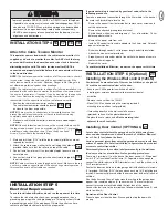
To prevent possible SERIOUS INJURY or DEATH, the collar MUST
be properly tightened. The door may not reverse correctly or limits
may be lost due to collar slip.

Alternate Mounting Kit 

(480LM OPTIONAL):

This kit allows model LM3800A to be mounted below the torsion bar in
the case where the torsion bar is not round or the normal mounting area 
is obstructed.

9

9a

Summary of Contents for LiftMaster LM3800A

Page 1: ...o LM3800A Instruktioner Garageportöppnare Modell LM3800A Ohjeet Autotallin oven avaaja Malli LM3800A Návody Pohon garážových vrat model LM3800A Obrázky Otvárač garážových vrát model LM3800A Útmutatók A LM3800A as modell garázsajtók haitós Upute Uređaj za otvaranje garažnih vrata Model LM3800A Instrukcje Napęd drzwi garażowych model LM3800A Instrucţiuni Dispozitiv de deschis uşa garajului modelul L...

Page 2: ...door balanced Do not let the garage door opener compensate for a binding or sticking garage door Sticking or binding doors must be repaired Garage doors door springs cables pulleys brackets and their hardware are under extreme tension and can cause serious personal injury Do not attempt to loose move or adjust them Call for garage door service Do not wear rings watches or loose clothing while inst...

Page 3: ...are not included in the carton This operator is compatible with Doors that use a torsion bar springs and a door no more than 4 2m high 80mm 178mm drums NOT TO BE USED on tapered drums over 152mm High lift and standard lift sectional doors up to 4 2m high Doors up to 5 5m wide Doors up to 16m2 25mm 1 torsion bar only Review or inspect proposed installation area Opener can be installed on left or ri...

Page 4: ... Head Screw 8x1 2x Self Tapping Screw 10 32 2x Wall Anchor 4x Handle 1x Rope 1x Insulated Staples 20x Bracket 1x Bit 1x 5 6 ASSEMBLY STEP 1 Attach the Collar to the Motor Unit To avoid installation difficulties do not run the door operator until instructed to do so Loosen the collar screws 1 Attach collar to either the left or the right side of the motor unit Ensure that the collar is seated all t...

Page 5: ...perator by sliding the collar over the torsion bar until pilot holes align with bracket Securely tighten collar screws that attach to the torsion bar to 16Nm 19Nm of torque Securely tighten both set screws firmly without damaging the motor unit 5 Fasten bracket securely with screws Tighten all mounting bracket hardware NOTE The motor unit does not have to be flush to wall 10 11 11 To prevent possi...

Page 6: ...onduit cut to proper length and strip insulation Attach with wire nuts not provided Properly secure wire under plastic ties so that wire does not come in contact with moving parts Reinstall the cover To avoid installation difficulties do not run the opener at this time To prevent possible SERIOUS INJURY or DEATH from a falling door If possible use emergency release handle to disengage door ONLY wh...

Page 7: ...ravel Limits Travel limits regulate the points at which the door will stop when moving up or down Follow the steps below to set the limits NOTE Cable Tension Monitor must be installed To program the travel limits Adjust the position of the door by using the black and orange buttons Black moves the door UP open and orange moves the door DOWN close 24 25 26 27 28 1 Setting the UP position Press and ...

Page 8: ...ion and run the operator through 3 or 4 complete travel cycles to test adjustment If the unit continues to fail the Safety Reverse Test call for a trained door systems technician IMPORTANT SAFETY CHECK Test the Safety Reverse System after Each adjustment of limits or force controls Any repair to or adjustment of the door including springs and hardware Any repair to or buckling of the floor Any rep...

Page 9: ...d aligned 1 If open the door will close If closed it will open 2 If closing the door will reverse 3 If opening the door will stop 4 If the door has been stopped in a partially open position it will close 5 If obstructed while closing the door will reverse If the obstruction interrupts the sensor beam the operator wil click for five seconds 6 If obstructed while opening the door will stop 7 If full...

Page 10: ...ode If it is still flashing 5 times and motor unit moves 150 200mm 6 8 The unit s APE Absolute Positioning Encoder may need to be replaced for details contact your Chamberlain reseller Symptom Door reverses while closing Check for possible door obstructions and remove Check that the cable tension monitor is properly connected to the operator Replace the cable tension monitor Cable tension monitor ...

Page 11: ...t from the Wireless Wall Control Check the LED on the Wall Control to ensure the LED turns on when button is pushed If the LED is weak or not on Change the batteries Remove cover and replace with correct batteries If the LED turns on and is strong check to ensure the unit is programmed into the unit 3 The door operates from the Door Control but not from the remote control Is the door push bar flas...

Page 12: ... in materials and or workmanship will be repaired or replaced at Chamberlain s option at no cost to the owner for the repair and or replacement parts and or product Defective parts will be repaired or replaced with new or factory rebuilt parts at Chamberlain s option If during the warranty period the product appears as though it may be defective contact your original place of purchase This warrant...

Page 13: ...e przeczytać te wskazówki Brama musi być wyważona Bramy unieruchomione lub zakleszczone nie mogą być poruszane przy pomocy napędu bram garażowych lecz muszą być naprawione Bramy garażowe sprężyny bram kable podkładki uchwyty i szyny są wówczas pod bardzo dużym naprężeniem co może być przyczyną poważnych obrażeń Proszę nie podejmować prób zluzowania bramy jej poruszenia lub wyprostowania lecz zwróc...

Page 14: ...iały lub drobne części które nie wchodzą w zakres dostawy Ten napęd jest kompatybilny z Bramami posiadającymi oś lub sprężyny i nie wyższymi niż 4 2m Bębnami zwijającymi 80mm 178mm NIE UŻYWAĆ w przypadku stożkowych bębnów zwijających ponad 152mm Bramami łożyskowanymi u góry i standardowymi bramami sekcyjnymi do wysokości 4 2m Bramami do szerokości 5 5m Bramami do 16m Tylko osie 25mm 1 Sprawdzić pr...

Page 15: ...x Kołek 2x Kołek wkręcany 2x Uchwyt do odblokowania 1x Linka do odblokowania 1x Obejmy przybijane 20x Bit 1x 5 6 Etap montażu 1 Kołnierz luźny umocować na zespole silnikowym Aby podczas instalacji nie pojawiały się trudności napęd włączyć dopiero gdy instrukcja tego wymaga Zluzować śruby kołnierza luźnego Kołnierz luźny umocować na zespole silnikowym albo po prawej albo po lewej Upewnić się że koł...

Page 16: ...ości wiercić przez płytę stalową 4 Ponownie założyć napęd nakładając napęd na oś aż do ustawienia łożyska w stosunku do nawierceń Umieszczone na osi śruby kołnierza dobrze dokręcić z momentem obrotowym 16Nm 19Nm Dobrze dokręcić śruby oporowe nie uszkadzając przy tym zespołu silnikowego 5 Przy pomocy śrub 14 10x1 7 8 dobrze dokręcić łożysko Dokręcić wszystkie śruby montażowe Wskazówka Zespół silnik...

Page 17: ...adzić przez kanał kablowy odciąć na odpowiednią długość i odizolować Kable połączyć przy pomocy dołączonego zacisku świecznikowego Przewody zabezpieczyć taśmą izolacyjną tak aby nie stykały się z ruchomymi częściami Ponownie przykręcić obudowę Aby podczas montażu nie pojawiały się trudności napędu jeszcze nie podłączać i nie włączać Aby nie dochodziło do możliwych poważnych obrażeń lub śmierci pow...

Page 18: ...u W celu ustawienie pozycji końcowych należy postępować zgodnie z podanymi poniżej krokami Dla zaprogramowania pozycji końcowych Ustawić pozycję bramy za pomocą czarnego lub fioletowego przycisku Przy czarnym brama porusza się do góry OTW a przy fioletowym brama porusza się do dołu ZAMKN 24 25 26 27 28 1 Ustawianie pozycji OTW Nacisnąć i przytrzymać czarny przycisk do chwili gdy żółta LED zacznie ...

Page 19: ...zeszkodzie 50mm lub płaskiej belce zmienia kierunek usunąć przeszkodę i w celu sprawdzenia ustawień 3 4 razy uruchomić napęd tak by wykonał cały cykl Jeżeli napęd ponownie nie spełni zabezpieczającego testu zmiany kierunku skontaktować się ze specjalistą od bram Ważny test bezpieczeństwa Zabezpieczający system zmiany kierunku testować po każdym ustawianiu pozycji końcowych lub siły każdej naprawie...

Page 20: ... brama jest zatrzymywana 4 Jeżeli brama jest zatrzymana w pozycji częściowo otworzonej jest zamykana 5 Jeżeli w trakcie zamykania brama zostanie zablokowana ruch bramy przełączany jest na odwrotny Jeżeli przeszkoda przerwie promień zapory świetlnej napęd klika przez 5 sekund 6 W razie zablokowania bramy przy otwieraniu jest ona zatrzymywana 7 Jeżeli brama jest całkowicie otworzona to nie jest zamy...

Page 21: ...enić APE Absolute Positioning Encoder odnośnie do szczegółów proszę skontaktować się ze swoim sprzedawcą firmy Chamberlain Objaw Brama w trakcie procesu zamykania zmienia kierunek ruchu sprawdzić czy przeszkoda blokuje bramę i usunąć ją sprawdzić czy przełącznik z liną zwisającą jest prawidłowo podłączony do napędu wymienić przełącznik z liną zwisającą Działa przełącznik z liną zwisającą Możliwa a...

Page 22: ...z nadajnikiem ręcznym ale nie działa z radiowym przyciskiem ściennym sprawdzić LED na przycisku ściennym czy włącza się ona po naciśnięciu przycisku Jeżeli LED świeci słabo lub w ogóle się nie zapala wymienić baterie Zdjąć obudowę i założyć właściwe baterie Jeżeli LED świeci wyraźnie sprawdzić czy przycisk ścienny został wpisany 3 Brama działa z przyciskiem ściennym ale nie działa z nadajnikiem rę...

Page 23: ...ostępnym dla kupującego i ani firma Chamberlain ani filie lub sprzedawcy firmy nie odpowiadają za jakiekolwiek szkody dodatkowe lub następcze wynikające z wszelkich wyraźnych lub domyślnych gwarancji odnośnie do tego produktu Ani przedstawiciel ani inne osoby nie są uprawnieni do przejmowania w imieniu firmy Chamberlain jakiejkolwiek odpowiedzialności w związku ze sprzedażą tego produktu 1 model 9...

Page 24: ... S taple Torsion Bar Staples Lock Screw 1 4 20 x 1 2 2 Roller TOP DRILL 8mm DRILL 19mm DRILL 8mm 132A2505 TOP DRILL 5 16 DRILL 3 4 DRILL 5 16 132A2505 80mm NOTICE WARNING 1 2 4 4 3 WHiTE GREEN WHiTE GREEN 1 3 2 2 6 5 cm 15 cm 1 Cable Tension Monitor Cable Tension Monitor Roller Center Cable 5 12 7 cm Drum Motor 1 8 1 4 3 mm 6 mm 3 4 Min 18 mm Min 1 2 18 mm Min 1 2 3 1 2 3 1 2 3 4 5 S crew 10 32 HA...

Page 25: ... stop door at desired DOWN position BLACK PURPLE Figure 4 or LOCK LIGHT Black Button BLACK PURPLE Push and hold until the door is at desired UP position Figure 2 Figure 3 Push either button to stop door at desired DOWN position BLACK PURPLE Figure 4 or LOCK LIGHT Black Button 2 3 1 23 24 25 26 27 29 30 31 32 33 34 35 36 37 38 40 2 80mm 3 CM475 1 22 28 7 9 8 5 78LM 770E 760E 9747E 94335E 3 10 10002...

Reviews: