background image

10

W I R I N G   A N D   H O O K U P

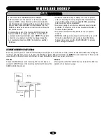
AC POWER HOOKUP (120/230 Vac)

Be sure your main power is OFF before attempting to hook up the ac power. The ac wiring should be attached to the wires exiting the 
conduit or pedestal post. Only use UL approved 14AWG (or larger) 600 volt insulated wire. 

NOTE: 

Do not connect any of the ac power 

wires directly to the electronic control board. Connect the batteries after the ac power is restored. 

120 Vac

Connect the BLACK wire to the incoming 120 Vac hot lead and 
connect the WHITE wire to the incoming neutral lead. Connect the 
GREEN wire to the ground.

230 Vac

Please purchase the 120 to 230 Vac conversion kit for 230 Vac 
operation. See Accessory page.

To reduce the risk of SEVERE INJURY or DEATH:
•  ANY maintenance to the operator or in the area near the 

operator MUST not be performed until disconnecting the 
electrical power and locking-out the power via the operator 
power switch. Upon completion of maintenance the area 
MUST be cleared and secured, at that time the unit may be 
returned to service.

•  Disconnecting power at the fuse box BEFORE proceeding. 

Operator MUST be properly grounded and connected in 
accordance with local electrical codes. 

NOTE:

 The operator 

should be on a separate fused line of adequate capacity.

•  ALL electrical connections MUST be made by a qualified 

individual.

•  DO NOT install ANY wiring or attempt to run the operator 

without consulting the wiring diagram. We recommend that 
you Install an optional reversing edge BEFORE proceeding 
with the control station installation.

•  ALL power wiring should be on a dedicated circuit and well 

protected. The location of the power disconnect should be 
visible and clearly labeled.

•  ALL power and control wiring MUST be run in separate 

conduit.

•  BEFORE installing power wiring or control stations be sure to 

follow ALL specifications and warnings described below. 
Failure to do so may result in SEVERE INJURY to persons 
and/or damage to operator. 

120 Vac

Neutral (White)

Neutral

Hot (Black)

Ground (Green)

Ground

120 Vac

Duplex 
Outlet Box

ATTENTION

AVERTISSEMENT

AVERTISSEMENT

AVERTISSEMENT

WARNING

CAUTION

WARNING

WARNING

WARNING

PRECAUCIÓN

ADVERTENCIA

ADVERTENCIA

ADVERTENCIA

Summary of Contents for LiftMaster MEGA SLIDE-X

Page 1: ...AL DUTY SLIDE GATE OPERATOR OWNER S MANUAL THIS UNIT IS A CLASS 1 2 3 OR 4 SLIDE GATE OPERATOR FOR USE IN SLIDE GATE APPLICATIONS The Chamberlain Group Inc 845 Larch Avenue Elmhurst Illinois 60126 119...

Page 2: ...cess Control Device 18 Dual Direction as Entry and Free Exit 18 CONTROL BOARD LAYOUT Component Locations 19 REPAIR PARTS 20 ACCESSORIES 21 SAFETY ACCESSORIES FOR SECONDARY ENTRAPMENT PROTECTION 22 REP...

Page 3: ...e motor allowing the gate to be manually opened Normal Operation Position Manual Release Position I N T R O D U C T I O N CARTON INVENTORY Before beginning your installation check that all components...

Page 4: ...thods must be designed arranged or configured to protect against entrapments in both the open and close directions of gate travel For Example For a slide gate system that is installed on a single fami...

Page 5: ...tivation must be located at least six feet 6 away from any moving part of the gate and where the user is prevented from reaching over under around or through the gate to operate the controls Outdoor o...

Page 6: ...op photo beam should be installed along the gate s path that is covered when open Photo beams are to be installed according to their manufacturer s instructions and are to be placed in areas that pose...

Page 7: ...both inside and outside of a vehicular horizontal slide gate Non contact sensors such as photo eyes must protect during both open and close gate cycles Injuries occur when people put their hands and a...

Page 8: ...t Direct drive gear reducer eliminates many parts that might otherwise fail State of the art MOSFET motor drive technology NO contactors or relays Dynamic motor braking to preserve gate stopping point...

Page 9: ...UITS Use the open area in base of the unit to position your conduits 12 0 wide by 10 75 deep Use 1 2 or 3 4 inch UL listed conduits Please observe any requirements in your local electrical code NOTE D...

Page 10: ...e cleared and secured at that time the unit may be returned to service Disconnecting power at the fuse box BEFORE proceeding Operator MUST be properly grounded and connected in accordance with local e...

Page 11: ...or 5 minutes after 2nd sequential obstruction then turns itself off however operator will require a reset signal to J5 4 to re activate gate In addition cycling the ac power will also reset unit Termi...

Page 12: ...rol detectors receivers keypads timers etc wires to it must also be run to the same terminals of the second Along with these control wires both operators MUST share a common ground connection from cha...

Page 13: ...of the slide gate to reduce the possibility of injury to persons that may attempt to walk through gate opening Along with the beams it is strongly recommended that pressure sensing edges be installed...

Page 14: ...ed by turning the IRD1 to the right CW more sensitive or left CCW less sensitive in small increments ADJUSTMENT While running the gate open and closed verify that the gate travels as expected Verify t...

Page 15: ...a screwdriver Re connect power to opener Figure 2 2 Press and release the learn button on the receiver The learn indicator light will glow steadily for 30 seconds 3 Within 30 seconds press and hold t...

Page 16: ...trol Board Layout page Replace batteries with LiftMaster P N MBAT batteries Replace in pairs BATTERY DISPOSAL Replaced batteries must be treated as a hazardous waste and disposed of in accordance with...

Page 17: ...VERTENCIA ADVERTENCIA Gate will not operate Is the HBEAT flashing Check the battery connections Check fuse F4 Replace if blown No Is the battery lo LED on Is the HBEAT flashing now Yes Is S2 8 open on...
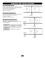
Page 18: ...n inputs DUAL DIRECTION AS ENTRY AND FREE EXIT Dual direction is a combination of both of the above configurations to provide the ability for traffic to enter or exit in the same lane Figure 3 RECOMME...

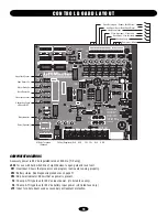
Page 19: ...C2 C3 C4 C1 U4 R12 S1 D6 OPEN D5 BRAKE D4 CLOSE D3 CLS D2 IRD OPEN 2 D16 R3 OPEN 3 D17 AUX 4 D18 SAFETY 5 D19 CLOSE 6 D22 BACK 7 D23 SHADOW 8 D24 OPEN CLOSE MANUAL R1 R9 R38 R15 R37 C8 C2 C12 U12 U1 R...

Page 20: ...043 Limit Nuts 11 MS013 Detent Plate 12 MS014 Siren 100 db 13 MS015 Transformer 120 230 Vac 24 Vac 14 MS016 120 Vac Duplex Outlet 120 Vac Only 15 MS018 Idler Pulley Bolt Washer and Nut 16 MS019 120 Va...

Page 21: ...1 Heater Option 150 watt with thermostat MBAT Replacement Battery 1 12V 7Amp Battery 2 required per operator MA200 SAMSKIT K1 Relay Output Option Accessory relay for external signaling common N C N O...

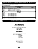
Page 22: ...23 Miller Edge Normally open contact MG 020 Miller Edge Normally open contact MG020 Miller Edge Normally open contact MGR20 Miller Edge Normally open contact MGS20 Miller Edge Normally open contact HO...

Page 23: ...A PARTICULAR PURPOSE ARE LIMITED IN DURATION TO THE 2 YEAR LIMITED WARRANTY PERIOD SET FORTH ABOVE EXCEPT THE IMPLIED WARRANTIES WITH RESPECT TO THE COVER AND CHASSIS WHICH ARE LIMITED IN DURATION TO...

Page 24: ...and operator required _____ This class operator is approved for the application of the operator 1 2 3 or 4 required _____ A sphere with a 2 1 4 diameter cannot be pushed through the gate or fixed pan...

Reviews: