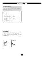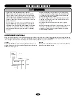
Flip switch up for
normal operation.
Flip switch down to
disengage power to
motor and for manual
operation.
3
MANUAL RELEASE
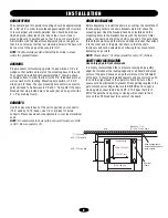
The MANUAL RELEASE switch is located on the left side of the
gate operator frame towards the chain. To operate the gate
manually, place the MANUAL RELEASE switch in the down
position. This will remove power to the motor allowing the gate to
be manually opened.
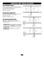
Normal Operation
Position
Manual Release
Position
I N T R O D U C T I O N
CARTON INVENTORY
Before beginning your installation check that all components
were provided and received undamaged. Refer to list below
for factory provided parts.
Description
Qty.
Operator
1
Accessory
Shelf
1
Owner’s
Manual
1
Gate Pull Tabs with Hardware
2
(MS205 Pull Tabs, MS204 Chain Bolt)
20' (6.1 m) of #41 Nickel Plated Drive Chain
1
(10' (3.05 m) coils, 2 required MS202)
Warning
Signs
2
Sealed 12 Vdc, 7AH Batteries
2

