background image

18

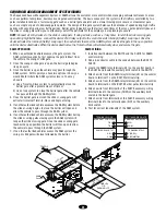
RADIO RECEIVER

All inputs are normally open and momentary, except the stop 
(N.C.). The following instructions are based upon UL325, and 
include recommendations for significant increase in safety.

We strongly recommend that you follow the UL guidelines 
presented throughout the manual. Refer to instructions shipped 
with optional control devices for mounting, wiring, programming 
and adjustment.

When using a remote control or Single Button Control Station in 
lieu of the Soft Open feature, perform the following 
modifications to the operator:

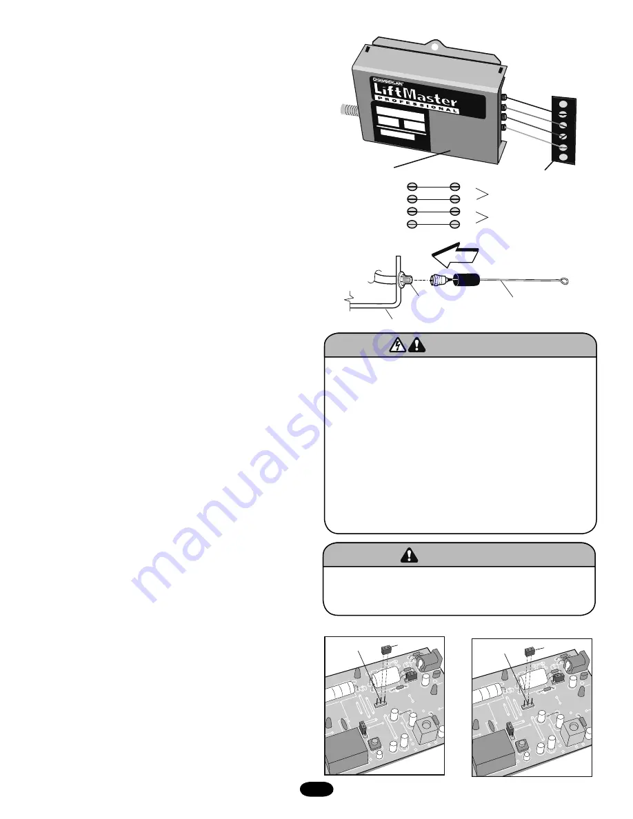
1.   Remove the green wire from R4 of the radio block and mount 

the wire to terminal block TB1 position 6.

2.   Move the brown wire on Terminal Block TB1 position 6 (from 

radio block R4) to Terminal Block TB1 position 1.

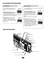
24Vac Accessory Power 

can be found at terminals R1 and R2 

located on radio terminal block.

The LiftMaster Radio Receiver comes pre-wired to the operator

•  Remove the brass antenna from the accessary box and screw it 

onto the “F”-connector provided on the side of the gate 
operator.

NOTE: 

The radio receiver is wired in the factory for single button 

control to open and close the gate. Remote control devices are 
not included.

R1    R2     R3    R4 

RADI

O RC

VR. 

4

3

2

1

R4

R3

R2

R1

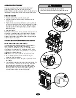
PROGRAMMING THE RADIO RECEIVER

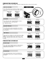
Set Security Mode

The Universal Receiver can be used with up to 15 rolling code 
remote controls or passwords in HIGH security mode. Alternately, 
it can be used with up to 31 of any type remote control in 
NORMAL security mode, including any combination of rolling 
code, billion code, or dip switch remotes.

The jumper must be set at the HIGH position for the receiver to 
operate in HIGH security mode. It must be set at NORMAL 
position to operate at the NORMAL mode (Figure 1).

When changing from NORMAL to HIGH security mode, any 
previous remote control codes must be erased. Repeat Steps 2 
and 3 in the Programming Section (see page 19) to reprogram the 
receiver for each remote control remote control in use.

The receiver is factory set at HIGH.

Set Output Duration

For commercial applications, the receiver can be set for either 
constant or momentary closure on the output contacts. Use of 
constant closure is prohibited on residential garage door openers 
because it overrides the safety reversal devices.

With the jumper in the "M" (Momentary) position, the contacts will 
close for 1/4 second regardless of the length of radio 
transmission. With the jumper in "C" (Constant) position, the 
contacts will stay closed as long as the radio continues 
transmitting (Figure 2).

The receiver is factory set at M.

To prevent possible SERIOUS INJURY or DEATH from 
electrocution:
•  Be sure power is not connected BEFORE installing the 

receiver.

To prevent possible SERIOUS INJURY or DEATH from a 
moving gate or garage door:
•  ALWAYS keep remote controls out of reach of children. 

NEVER permit children to operate or play with remote 
controls.

•  Activate gate or door ONLY when it can be seen clearly, is 

properly adjusted and there are no obstructions to door travel.

•  ALWAYS keep gate or garage door in sight until completely 

closed. NEVER permit anyone to cross path of moving gate or 
door.

ATTENTION

AVERTISSEMENT

AVERTISSEMENT

AVERTISSEMENT

WARNING

CAUTION

WARNING

WARNING

WARNING

PRECAUCIÓN

ADVERTENCIA

ADVERTENCIA

ADVERTENCIA

FIGURE 1

To prevent possible SERIOUS INJURY or DEATH, the use of 
CONSTANT OPERATION on residential openers is PROHIBITED.

ATTENTION

AVERTISSEMENT

AVERTISSEMENT

AVERTISSEMENT

WARNING

WARNING

CAUTION

WARNING

WARNING

PRECAUCIÓN

ADVERTENCIA

ADVERTENCIA

ADVERTENCIA

Security Mode 
Terminals

Jumper

HIGH

SECURITY  MODE

Relay Control

24Vac Power

Antenna

Connector

Accessory Tray

Security Mode 
Terminals

Jumper

NORMAL

SECURITY  MODE

Receiver

Operator
Terminal

Summary of Contents for LiftMaster Professional SL575

Page 1: ..._____________ located on electrical box cover Installation Date__________________ 2 YEAR WARRANTY MODEL SL575 IS FOR VEHICULAR PASSAGE GATES ONLY AND IS NOT INTENDED FOR PEDESTRIAN PASSAGE GATE USE MO...

Page 2: ...y instructions CARTON INVENTORY Before beginning your installation check that all components were supplied and received undamaged Refer to list below for factory supplied parts HARDWARE KIT K77 34846...

Page 3: ...30 ft 9 1 m 1 HP Motor Maximum Cycle Rate 18 cycles per hour At Maximum Gate Weight Maximum Gate Speed 10 sec 25 4 cm sec Maximum Gate Weight 1800 lbs 816 5 kg Maximum Cantilever Gate Width 32 ft 9 8...

Page 4: ...protection Type C Inherent adjustable clutch or pressure relief valve Type D Connections provided for a control requiring continuous pressure to operate the operator open and close Type E Built in aud...

Page 5: ...nded for user activation must be located at least six feet 6 away from any moving part of the gate and where the user is prevented from reaching over under around or through the gate to operate the co...

Page 6: ...y Loop 4 1 2 m Typical Photo eye for open cycle Photo eye for close cycle 8 2 4 m Open Edge Telephone Entry System 1 1 2 37 mm 1 4 6 mm or larger for loop wire width depending on loop wire size STREET...

Page 7: ...both inside and outside of a vehicular horizontal slide gate Non contact sensors such as photo eyes MUST protect during both open and close gate cycles Injuries occur when people put their hands and a...

Page 8: ...control station installation ALL power wiring should be on a dedicated circuit and well protected The location of the power disconnect should be visible and clearly labeled ALL power and control wirin...

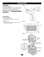
Page 9: ...2 2 Locate electrical conduit as required prior to pouring concrete 3 Pour concrete pad 4 Secure operator Figure 3 to the concrete pad using four 1 2 concrete anchors not provided Figure 1 Figure 2 Fi...

Page 10: ...d pipe Posts should be parallel and square to the gate Figure 2 2 Locate electrical conduit as required prior to pouring concrete 3 Secure operator Figure 3 to posts using four 3 7 6 cm U bolts and ha...

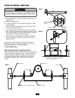
Page 11: ...ck for every 10 3 m of chain length Do not overtighten chain NOTE ABOUT SOME TYPES OF CANTILEVER GATES With some cantilever gates over 20 6 m long you may need to add a brace along the length of the g...

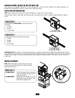
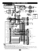
Page 12: ...ire gauges Secure all electrical power connections inside the disconnect switch electrical box Refer to electrical wiring diagrams on pages 30 and 32 115VOLT 1 PH USE COPPER CONDUCTO R ONLY 115VOLT 1...

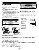
Page 13: ...entered over the magnet wheel Adjust with horizontal screws 2 The sensor must be level 3 The sensor air gap should be adjusted to 010 015 of an inch The thickness of a business card may be used to gau...

Page 14: ...input photo eye is cleared the gate continues to open Activating this input when the gate is closing will have no effect Terminals 10 5 Obstruction While Closing Edge Photo Eye Input Edge Input See P...

Page 15: ...put functions to reverse the gate to the open limit when activated during the close cycle The entrapment is not cleared at the limit and the Timer to Close will be disabled The Timer to Close may be e...

Page 16: ...This switch enables the Maglock feature On an open command there will be a half second delay after the maglock relay is released before the motor starts WARNING ENABLE This switch enables the gate in...

Page 17: ...hroughout the manual Installation device instructions Always follow the instructions provided by the manufacturer when installing and adjusting any control device If these instructions are contrary to...

Page 18: ...erate at the NORMAL mode Figure 1 When changing from NORMAL to HIGH security mode any previous remote control codes must be erased Repeat Steps 2 and 3 in the Programming Section see page 19 to reprog...

Page 19: ...ERASE ALL REMOTE CONTROL CODES Press and hold the learn button on the receiver panel until the indicator light turns off about 6 seconds All remote codes are now erased Then follow the steps above to...

Page 20: ...additional surge protection MASTER SECOND SYSTEMS Dual Gate Communications The control board is capable of running the operator in a master or second mode depending on S4 switch setting Before initia...

Page 21: ...h ground rod must be located within 3 feet from the gate operator Use the proper type earth ground rod for your local area The ground wire must be a single whole piece of wire Never splice two wires f...

Page 22: ...le or pair of slide swing gate operator The design of this gate system balances the demands of speed during high traffic periods with security during low traffic periods Barrier gates typically have t...

Page 23: ...perator Failure to adjust and retest the gate operator properly can increase the risk of INJURY or DEATH 5 Use the emergency release ONLY when the gate is not moving 6 KEEP GATES PROPERLY MAINTAINED R...

Page 24: ...LEARN FUNCTION FORCE PROFILE This function is preprogrammed at factory If either board or motor is replaced the control board will need to be reprogrammed to LEARN the specific motor RPM profile of yo...

Page 25: ...n when Stop switch is not activated D19 Soft Open On when Open switch is activated D21 Hard Open On when Open switch is activated D24 Interrupt Safety Loop On when Interrupt Safety Loop activated D29...

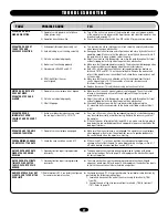
Page 26: ...good check to make sure that the J2 connector is making good contact with the pins on the control board If all is good replace the control board 1 Transformer s secondary is overloaded 2 Low primary h...

Page 27: ...it is adjusted correctly but continues to fail 1 Operator s manual release is not aligned 2 Clutch is not adjusted properly 3 V Belt Slippage Make sure that the unit s manual release is not engaged Th...

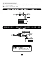
Page 28: ...adout is in degrees Celsius White Black L1 L2 Green Ground 1 T ck la B N ack l B ON OFF On Off Switch White Black 1 PHASE 115 VOLT POWER IN Line voltage to operator controls H E A T E R W I R I N G D...

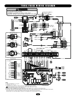
Page 29: ...VAC COMMON DC GND LOCK 1 LOCK 1 ALARM 1 ALARM 1 RADIO SHADOW VDC COM CLOSE STOP COM SOFT OPEN HARD OPEN INTERRUPT SAFETY OPEN CLOSE MASTER SECOND MAGLOCK 24 VAC INTERRUPT LOOP SAFETY EXIT LOOP FIELD...

Page 30: ...A CONTACTOR B A1 4 A1 ORANGE PURPLE OR P 1 2 L S A NC C L S B NC C YEL BLK Y BK GY TB2 BL Y PU GY BL Y PU 1 3 8 5 4 2 OL BK BK BK BK BL BK BL BK 115V BRAKE SOLENOID 115V CONNECTION 230V BRAKE SOLENOID...

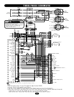
Page 31: ...IO 3 PHASE POWER IN ON OFF SWITCH GROUND SAFETY ALARM 100 db NOTES 1 Transformer primary voltage is the same as the operator line voltage Secondary 24V 60VA 2 Wire color 208V red 230V orange 460V purp...

Page 32: ...R4 TB2 AB TB2 CD FREE EXIT LOOP HARNESS 10 PIN TB1 8 TB1 3 TB2 AB TB2 CD INTERRUPT LOOP HARNESS 10 PIN 4 6 7 8 9 10 BK BK PU 7 8 9 4 5 6 460V CONNECTION 230V BRAKE SOLENOID 1 3 2 BL BK BL BK BK BK PU...

Page 33: ...MODEL DESCRIPTION G65MG0204 Miller MG020 2 wire electric edge for gates Sensitized on three sides Requires mounting channel 4 1 2 m long 24V ac dc G65MG0205 Miller MG020 2 wire electric edge for gates...

Page 34: ...h shaft kit Complete with Clutch shaft sprockets e ring compression spring pulley washer bearings retaining ring disconnect splined hub and roll pin NOT SHOWN 19 48047M Roller Chain Sprocket Reduction...

Page 35: ...35 35 5 6 10 K4 K75 34842 1 2 K1 71 B120 71 B208 71 B240 71 B575 K3 K75 34828 K2 K75 34824 K3 K75 34828 3 7 9 8 4 K6 K75 19977 K8 K72 34845 K7 K72 34844 K5 K29 32410 I L L U S T R A T E D P A R T S...

Page 36: ...75 75 21 SL575 75 81 SL575 100 21 SL575 100 81 25 2010 Overload 10 AMP SL575 50 11 25 2015 Overload 15 AMP SL575 100 11 25 4002 SK Overload 1 8 to 2 6 AMP SL575 100 53 NOT SHOWN K74 18379 RPM Sensor H...

Page 37: ...37 N O T E S...

Page 38: ...38 N O T E S...

Page 39: ...39 N O T E S...

Page 40: ...with new or factory rebuilt parts at Seller s sole option ALL IMPLIED WARRANTIES FOR THE PRODUCT INCLUDING BUT NOT LIMITED TO ANY IMPLIED WARRANTIES OF MERCHANTABILITY AND FITNESS FOR A PARTICULAR PU...

Reviews: