8 of 53
Doc 6001242 (01-20273)
Rev C
PART 2
SYSTEM INSTALLATION
A.
MOUNTING GATE OPERATOR
WARNING
For safety reasons, the Power Fail Operation Option is shipped with the battery unconnnected
to the system.
Do not connect the battery until all other installation and alignment
procedures have been completed.
Failure to observe this warning may result in the Power
Fail Operation Option moving the gate at unexpected moments.
To avoid injury, always turn off the unit power switch before working on gate.
1. Loosen the large mounting bolt and remove the Swing Arm Cap assembly.
2. Remove 4 protective bolts holding the cover on, lift off the cover and set aside.
3. Remove the assembly kit and parts.
4. Remove the 4 bolts that attach the gate operator to the shipping pallet.
5. Mount gate operator on the cement pad using the previously installed anchors. Be sure the
operator mounting is level and square, and that the gate operator control box faces away
from the gate.
6. Connect the power conduit into the switch box.
7. Reinstall the Swing Arm Cap assembly and finger tighten the large mounting bolt.
B. CONNECTING
POWER
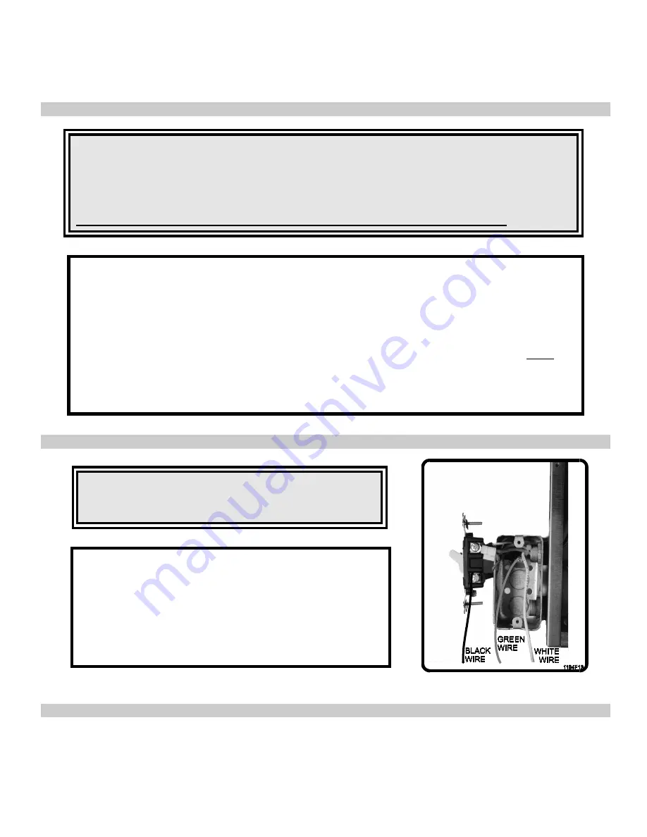
Figure 3. AC Wiring.
CAUTION
Ensure that the AC power circuit breaker is turned off
before wiring power to the switchbox.
Run power cables through the conduit to Gate Operator,
then connect wires to the switch box as shown in Figure 3:
1. Wire nut the hot (black) wire to the black pig tail.
2. Wire nut the neutral (white) wire to the white pig tail.
3. Wire nut the ground (green) wire to the green pig tail.
4. Dress all wiring inside the switch box and install cover.


