9
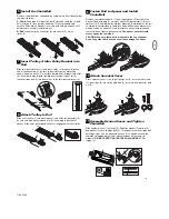
Setting the Force
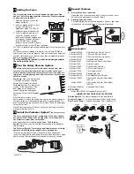
The force setting button is located behind the light lens of the
opener. The force setting regulates the amount of power required
to open and close the door.
1. Open the light lens. Locate the
orange button (2).
2. Push the orange button (2) twice
to enter unit into Force
Adjustment Mode. The LED (3)
(indicator light) will flash quickly.
3. Push the programmed remote
control (4) or push bar on the
door control that was shipped with
your opener. The door will travel
to the DOWN (close) position.
Push the remote control (4) again,
the door will travel to the UP (open) position.
The LED (3) (indicator light) will stop flashing when the force has been
learned.
The door must travel through a complete cycle, UP and DOWN, in
order for the force to be set properly. If the unit cannot open and close
your door fully, inspect your door to insure that it is balanced properly
and is not sticking or binding.
The force MUST be learned in order to properly complete
the setting of the limits.
26
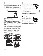
Test the Safety Reverse System
The safety reverse system test is important. Garage door must
reverse on contact with a 40mm obstacle laid flat on the floor.
Failure to properly adjust opener may result in serious personal
injury from a closing garage door. Repeat test once a month and
adjust as needed.
Procedure:
Place a 40mm obstacle
(1) laid flat on the floor under the
garage door. Operate the door in
the
down
direction. The door must
reverse on the obstruction. If the
door
stops
on the obstruction,
remove obstruction and repeat
Setting the Limits step 25.
Repeat
test.
When the door reverses on the
40mm obstacle, remove the obstruction and run the opener through a
complete travel cycle. Door
must not
reverse in closed position. If it
does, repeat
Setting the Limits and Force steps 25 and 26
and repeat
safety reverse test.
Place 20kg at the center of the door and ensure that the door will not
move up more than 500mm.
27
2
4
2
(2x)
3
1
Install the Protector System
™
(See accessories)
The force, as measured on the closing edge of the door, should
not exceed 400 N (40kg). If the closing force is more than 400 N,
the Protector System must be installed.
After opener has been installed and adjusted,
The Protector
System™
accessory can be installed. Instructions are included with
this accessory.
The Protector System™ provides an additional measure of safety
against a small child being caught under a garage door.
It uses an invisible beam which, when broken by an obstruction,
causes a closing door to open and prevents an open door from closing
and is
strongly recommended for homeowners with young children.
28
4
3
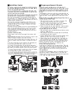
Special Features
A.
Door within a door connection
Open light lens. Locate auxiliary quick connect terminals. Insert
bell wire into quick connect terminals 1 and 2.
B.
Flashing light connection
The flashing light can be installed anywhere. Connect light leads
to quick connect terminals 3 and 4. Terminal 4 is ground.
29
Accessories
(1) Model 94330E
Single-Function Remote Control
(2) Model 94333E
3-Function Remote Control
(3) Model 94335E
3-Function Mini Remote Control
(4) Model 9747E
Keyless Entry System
(5) Model 78LM
Multi-Function Door Control Panel
(6) Model 760E
Outside Keylock
(7) Model 1702E
Outside Quick Release
(8) Model 770E
The Protector System™
(9) Model 1703E
The Liftmaster Arm™
(10) Model FLA230
Flashing Light Kit
(11) Model EQL01
Door Handle Quick Release
(12) Model 100027
1-Position Key Switch (Flush Mount -
100010)
Model 100041
2-Position Key Switch (Flush Mount -
100034)
(13) Model 16200LM
Pedestrian Door Switch
NOT SHOWN
Model MDL100LM
Mechanical Door Latch Kit
WIRING INSTRUCTIONS FOR ACCESSORIES
Outside Keylock –
To opener terminals: Red-1 and White-2
Protector System™ –
To opener terminals: White-3 and Grey-4
Door Control Panel –
To opener terminals: Red-1 and White-2
30
B
8
7
6
5
A
12
100027/100010
100041/100034
9
1703E
6
760E
94333E
2
94330E
1
5
78LM
LOCK
LIGHT
FLA230
10
13
94335E
3
16200LM
770E
8
1702E
7
11
EQL01/EQL02
4
9747E
114A3356

