background image

19

SAMS WITH OTHER OPERATORS

REQUIRES THE K1 RELAY OPTION (Order SAMS KIT)

This feature allows a logical interface between the MEGA ARM barrier gate and a 
swing, slide, etc. gate operator (or MTC-31). All that is required is 4 wires between the 
MEGA ARM barrier gate and the other operator. It will be necessary to have one set 
of dedicated/isolated dry contacts - {C. and N.C.} COMMON and NORMALLY CLOSED 
be available at the other operator’s OPEN LIMIT SWITCH. Most operators will require 
that this EXTRA limit switch be added to their open limit switch assembly.

OPERATION 

A one second pulse from access control device to the MEGA ARM will energize its K1 
relay sending an open signal to the other operator causing it to open. However, the 
MEGA ARM’s barrier arm will not raise yet. When the other operator reaches its full 
open limit switch, this will open the COMMON and NORMALLY CLOSED contact on the 
EXTRA open limit switch. This will allow the original signal from your access control 
device (that was stored in memory) to now raise the barrier arm. As long as the 
other operator is in the full open position, any additional open pulse sent will in turn 
energize the MEGA ARM’s K1 relay to send another open signal to the other 
operator as well as cause the arm to raise again if it has closed via a car crossing 
the MEGA ARM’s close loop.

WIRING: 

 1.   Run 2 wires from the other operator’s isolated common & normally closed 

contacts of its open limit switch to the MEGA ARM J5#8 and one of the 
commons J5, #9-12. 

 2.   Run 2 wires from the MEGA ARM’s K1 relay (common & normally open) to the 

other operators common and open input. (

WARNING:

 Max of 30 VOLTS at .5 

amps through relay). J5 #8 was the unused SHADOW LOOP input on the MEGA 
ARM. 

NOTE: 

A separate open device (24 hour timer, toggle switch) can be run 

to the other operator to control it without raising the gate arm. Tampering with 
the other operator’s safety loops, safety edges and reverse sensors WILL NOT 
cause the arm to raise if one tripped. The arm will only raise if an intended 
open signal was sent to the MEGA ARM.

NOTES:


 •   For motorized teeth, vertical pivot or overhead operator, leave S1-6, S1-8 OFF 

(this will keep the K1 relay latched down until the arm reaches the down 
position. This will keep the other gate operator locked open or teeth locked 
down until the arm closes completely).

 •   In this mode, if the arm senses an impact, the K1 relay will stay energized 

holding open (or teeth down) the other operator until the arm times out and 
closes.

NOTE:

 Insert a jumper across the JP2 terminal to allow the SAMS feature to work 

with the multiple vehicle memory count selection, use the K1 relay to open the 
sequenced gate (S1-5 off, S2-6 on, jumper across JP2). This allows gate to store 
input counts via J5 #4 but not raise the arm until the sequenced slide or swing gate 
has fully opened.

K1 Relay

C

C

Access Device

Open Input

NO

NC

Other Operator
(Slide, Swing, Teeth, etc.)

S1, #6 and #8 (ON) = K1 Relay PULSE only.
S1, #6 and #8 (OFF) = K1 Relay LATCH only.

J5 #11

J5 #8

Extra Open Limit 
Switch

ADDITIONAL FEATURES »

 SEQUENCE ACCESS MANAGEMENT SYSTEM (SAMS) WITH "MEMORY"

SEQUENCE ACCESS MANAGEMENT 
SYSTEM (SAMS) WITH "MEMORY"

Summary of Contents for MADCBB

Page 1: ...ED IMPORTANT Read and understand Warranty Page first Batteries included MUST be connected for proper operation of operator Use 2 LiftMaster 12 Vdc 7AH Part MBAT MEGA ARM MEGA SPRINT MEGA ARM TOWER MEGA SPRINT TOWER The Chamberlain Group Inc 845 Larch Avenue Elmhurst Illinois 60126 1196 www liftmaster com ...

Page 2: ... Checkout 21 Gate Not Operating 21 Troubleshooting Chart 21 REPAIR PARTS 22 Part Numbers and Descriptions 22 Parts Shipped 22 Mega Arm Tower Unique Parts List 22 Mega Arm Options Parts List 22 ACCESSORIES 23 WARRANTY POLICY 24 TABLE OF CONTENTS When you see these Safety Symbols and Signal Words on the following pages they will alert you to the possibility of serious injury or death if you do not c...

Page 3: ...protection Type C Inherent adjustable clutch or pressure relief valve Type D Connections provided for a control requiring continuous pressure to operate the operator open and close Type E Built in audio alarm Examples include sirens horns or buzzers NOTE UL requires that all installations must have warning signs placed in plain view on both sides of the gate to warn pedestrians of the dangers of m...

Page 4: ...ation must be located at least six feet 6 away from any moving part of the gate and where the user is prevented from reaching over under around or through the gate to operate the controls Outdoor or easily accessible controls shall have a security feature to prevent unauthorized use 9 The Stop and or Reset if provided separately must be located in the line of sight of the gate Activation of the re...

Page 5: ...Timer To Close with on off selection Transient voltage protection on all inputs Wrench or Socket Set Phillips Head Screwdriver C Clamps FEATURES INTRODUCTION FEATURES TOOLS NEEDED OPERATOR SPECIFICATIONS Level Small Screwdriver T25 Torx Head Screwdriver TOOLS NEEDED During assembly installation and adjustment of the operator the tools listed below may be needed This model is intended for use in ve...

Page 6: ...e tower base plate The operator should be centered on the pad and spaced approximately 6 from the edge of the pad on drive way side in order to get the most reach out of arm Install conduits for the 120 230 Vac main power low voltage control wiring and one or two extra for loop sensor leads Conduit size should be limited to 1 2 when possible to reduce crowding if more than four are needed All cond...

Page 7: ...d in order to allow for the 1 2 thick base plate as well as washers for leveling Attach the operator to the concrete pad with appropriate fasteners 1 2 3 1 2 x 6 1 2 x 6 base plate base plate PEDESTAL INSTALLATION TOWER INSTALLATION Barrier Arm Gate Arm Bracket Operator INSTALL THE BARRIER ARM Line up the holes in the barrier arm with the slotted holes in gate arm bracket Insert the bolts through ...

Page 8: ...cal power and locking out the power via the operator power switch Upon completion of maintenance the area MUST be cleared and secured at that time the operator may be returned to service Disconnect power at the fuse box BEFORE proceeding Operator MUST be properly grounded and connected in accordance with local electrical codes NOTE The operator should be on a separate fused line of adequate capaci...

Page 9: ...ch in the ON position the Multiple Vehicle Memory will activate with inputs on terminal 4 and Common COM on the J5 terminal strip Use with laser scanners or card readers and transmitters with timed anti pass back With S1 switch 5 on this input becomes a momentary pulse open pulse close 5 SAFETY This input is generally not used with the MEGA ARM If used its function is to make gate reverse and go b...

Page 10: ...perator control board to the BLACK terminal of the OTHER battery Connect the jumper provided between the remaining terminals of each battery if one is not already in place IMPORTANT Do not run operator without installing the batteries Replace batteries in pairs using LiftMaster MBAT or 29 NP712 batteries Failure to install batteries correctly will cause damage and will not be covered by warranty R...

Page 11: ...then three wires will run between gates Figure 1 If it is required that if one gate senses an obstruction the other reverses also then 3 additional wires must be run between the primary J3 and second J3 Figure 2 These connections are for transmitting IRD obstruction signals between both operators This will allow the primary or second to inform the other that a closing obstruction has occurred and ...

Page 12: ...1 K1 D11 D12 R13 D14 U19 J4 F3 F4 F1 F2 1A DC IRD1 R63 BAT MOV MOTOR UX LIMITS J3 J5 M S JP2 S3 1 Q2 T2 1 2 3 4 5 6 7 8 9 1Ø 11 12 T1 OPEN 1 D15 C7 X2 C19 C2 C3 C4 U4 R12 OPEN 2 D16 R3Ø OPEN 3 D17 AUX 4 D18 SAFETY 5 D19 CLOSE 6 D22 BACK 7 D23 SHADOW 8 D24 OPEN CLOSE MANUAL R1Ø R9 R38 R15 R37 C8 C2Ø C12 U12 U1Ø R8 R7 R6 R5 U2 U3 CPU U5 U6 U7 X1 R4 R3 T4 T3 T6 T5 T8 T7 C15 C2 D27 Q6 Q5 F5 C22 C18 U1...

Page 13: ...CLOSE If the Close Loop detects tailgating the K1 Relay will activate If an anti tailgating alarm is wired into terminal strip J1 an alarm will sound NOTE When using the Clutch Option turn DIP switches S1 6 and S2 7 to the ON position Auto Close When this feature is activated the barrier arm will CLOSE by the timer whenever it is forced UP OPEN A B C HANDING THE BARRIER ARM DIP Switch S1 7 The J4 ...

Page 14: ...Vehicle Memory will activate with inputs on terminal 4 and Common COM on the J5 terminal strip Any of the terminals 9 12 on the J5 terminal strip can be used for common NOTE With Multiple Vehicle Memory activated the barrier arm will remain OPEN until the pre authorized number of vehicles pass over the Close Loop AUTO CLOSE DIP Switch S2 7 The S2 7 DIP switch Auto Close should be activated in case...

Page 15: ... to the open position time out using the time delay set at S 2 switches 1 5 and then close If arm is obstructed while opening the arm will stop time out using the time delay set at S 2 switches 1 5 and then close Turning the IRD1 right clockwise more sensitive or left counter clockwise less sensitive in small increments will allow sensitivity adjustments IF ARM DOES NOT REVERSE DO NOT CONTINUE TO ...

Page 16: ...ly If drilling is required DO NOT DAMAGE THE SHAFT use a drill bit smaller than the small hole size of the pin Correct pin P N MA013 is a 2 pin with a number 6 taper only NEVER USE A BOLT AS A TEMPORARY FIX THIS WILL DAMAGE THE SHAFT AND COLLAR BATTERY BATTERY DISPOSAL Replaced batteries must be treated as a hazardous waste and disposed of in accordance with State Local and Federal Regulations See...

Page 17: ...s backaway free exit Terminal 6 is close input ENTRY WITH ACCESS CONTROL DEVICE Gate will open when activated by an access control device When vehicle passes and clears close loop gate will close NOTE If a second vehicle tail gates and is sensed at the close loop gate will stop its closing motion until loop is cleared again Terminal 6 is close input Terminals 1 2 and 3 are open inputs DUAL DIRECTI...

Page 18: ...here 1 is up and 0 is down SET THE DIP SWITCHES AT THE SECOND OPERATOR 1 Set switch bank S1 to 00100000 where 1 is up and 0 is down 2 Set switch bank S2 to 00100010 where 1 is up and 0 is down S1 1 ON 2 3 4 5 6 7 8 1 ON 2 3 4 5 6 7 8 Close Loop S2 OFF ON ON ON ON ON ON ON ON ON ON ON ON ON OFF OFF 1 ON 2 3 4 5 6 7 8 1 ON 2 3 4 5 6 7 8 S1 S2 OFF OFF ON ON ON ON ON ON OFF OFF ON ON ON ON ON ON RECON...

Page 19: ...M J5 8 and one of the commons J5 9 12 2 Run 2 wires from the MEGA ARM s K1 relay common normally open to the other operators common and open input WARNING Max of 30 VOLTS at 5 amps through relay J5 8 was the unused SHADOW LOOP input on the MEGA ARM NOTE A separate open device 24 hour timer toggle switch can be run to the other operator to control it without raising the gate arm Tampering with the ...

Page 20: ...D3 CLS D2 IRD OPEN 2 D16 R3Ø OPEN 3 D17 AUX 4 D18 SAFETY 5 D19 CLOSE 6 D22 BACK 7 D23 SHADOW 8 D24 OPEN CLOSE MANUAL R1Ø R9 R38 R15 R37 C8 C2Ø C12 U12 U1Ø R8 R7 R6 R5 U2 U3 CPU U5 U6 U7 X1 R4 R3 D8 T4 T3 T6 T5 T8 T7 C15 C2 D27 Q6 Q5 F5 C22 C18 U18 1 2 3 4 5 6 7 8 S2 1 2 3 4 5 6 7 8 D1Ø R14 R18 R21 R24 R36 R42 R47 R53 R35 R41 R46 R5Ø R61 C16 R17 R16 D29 Q4 D28 D26 C6 D25 B2 U8 U9 U16 U11 U13 U14 U1...

Page 21: ...t connected set with R63 shown on the Control Board Layout page TROUBLESHOOTING BATTERY CHECKOUT GATE NOT OPERATING GATE NOT OPERATING GATE WILL NOT OPERATE Check the battery connections Clear the active input to allow the gate to open Clear the active input to allow the gate to close The max timer MRT has expired Remove AC and battery power then reapply to reset Inspect the belt for slippage and ...

Page 22: ... Nylon Arm Nuts 2 MA022 Arm Bolts 2 MA023 Gate Arm 12 73A3 Filter Module 74 31243 Surge Suppressor 20 MA036 Collar 21 MA037 Nylon Washer parts not shown 1 2 3 4 5 6 7 8 9 10 11 12 13 14 15 16 17 18 18 19 20 21 PARTS SHIPPED ITEM QTY MEGA ARM Operator 1 Controller 1 Operator Cover 1 Installation and Service Manual 1 Arm Bolts with Washers 2 Nylon Nuts 10 7AH Batteries 2 MEGA ARM TOWER UNIQUE PARTS ...

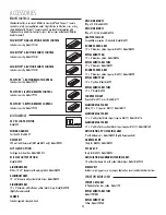
Page 23: ...D PADDED ARM 14 x 4 diameter yellow requires MA031 Model MA028 REPLACEMENT PAD 14 x 4 yellow Model MA029 REPLACEMENT ARM TUBE 14 x 4 Model MA030 COUNTER WEIGHT Required for all 15 arms Model MA117 ALUMINUM GATE ARM 15 x 3 with yellow black stripes requires MA117 Model MA116 ALUMINUM GATE ARM 15 x 3 with reflective yellow black stripes requires MA117 Model MA116R ALUMINUM GATE ARM White 15 x 3 requ...

Page 24: ...pecifically disclaims any and all implied warranties merchantability or fitness for a particular purpose It is the purchasers sole and exclusive responsibility to determine whether or not the equipment will be suitable for a particular purpose In no event shall LiftMaster inc be held liable for direct indirect incidental special consequential damages or loss of profits whether based on contract to...

Reviews: