background image

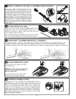
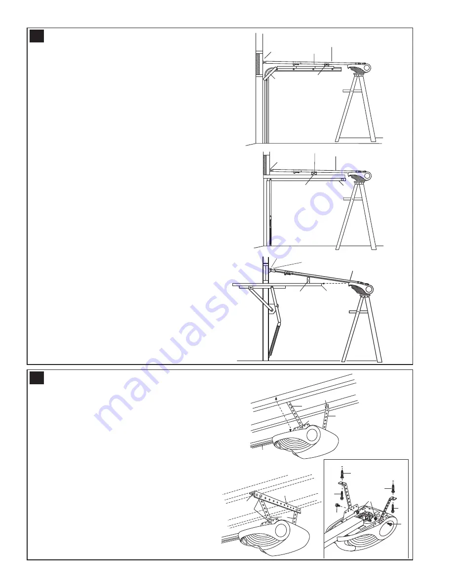
POSITION THE OPENER

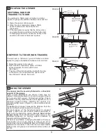
SECTIONAL DOOR OR
TRACKED TILT DOOR

You will need a 50mm piece of timber or similar
spacer to gauge the distance between door and rail.

1. Raise the opener onto support.
2. Open the door completely, place a 50mm

spacer between the door and the rail
(as shown).

3. If the top section or panel hits the trolley when

you raise the door, pull down on the trolley arm
to disengage the motor. Leave the trolley in this
position until motor is fastened in place.

ONE PIECE TILT DOOR (NON TRACKED)

You will need a 100mm (4”) piece of timber or similar
spacer to gauge the distance between door and rail.

1. Raise the opener onto support.
2. Open the door completely, place a 100mm

spacer between the door and the rail
(as shown).

3. The top of the door should be level with the top

of the motor. Do not position the opener more
than 50mm (2”) above this point.

HANG THE OPENER

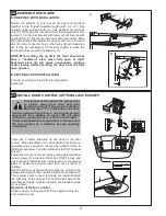
The opener must be securely fastened to a structural
support of the garage.
Three typical installations are shown. Yours may be
different. Hanging brackets (1) should be angled (Figure
A) to provide rigid support. On finished ceilings, (Figure
B) attach a sturdy metal bracket (not supplied) (4) to a
structural support before installing the opener. For
concrete ceiling mount, (Figure C), use concrete anchors
provided.
On each side of opener measure the distance from the
opener to the structural support (or ceiling).
Cut both pieces of the hanging bracket to required
lengths. Flatten one end of each bracket and bend or
twist to fit the fastening angles. Do not bend at the
bracket holes. 
Drill 4.5mm (3/16") pilot holes in the
structural supports (or ceiling). Attach brackets to
supports with wood screws (2).
Lift opener and fasten to hanging brackets with screw,
lock washer and nut (3). Check to make sure rail is
centred over the door. REMOVE 50mm or 100mm board.
Operate door manually. If door hits the rail, raise header
bracket. Use rail grease and lubricate bottom surface of
rail (5).

A

2

1

1

3

4

2

3

4

2

3

3

C

B

4

2

1

3

5

16

15

6

Rail

Door

50mm spacer should
be used to determine
the correct mounting
position

Header
Bracket

50mm (2”)

above the highest

point of travel

Header
Bracket

50mm spacer should
be used to determine
the correct mounting
position

50mm (2”)

above the highest

point of travel

Door

Rail

100mm spacer should
be used to determine
the correct mounting
position

Door

Header

200mm (8”)

above the highest

point of travel

Bracket

Rail

Door A

Door B

Door C

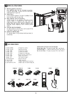
Summary of Contents for merlin MT1000

Page 1: ...reference www chamberlainanz com MT600 MT1000 Sectional and Tilt Garage Door Opener Installation and Operating Instructions This manual contains IMPORTANT SAFETY information DO NOT PROCEED WITH THE IN...

Page 2: ...e door a CM1702 outside quick release must be installed This accessory allows manual operation of the garage door from outside in case of power failure Keep garage door balanced Do not let the garage...

Page 3: ...Nut 14 Ring Fastener 15 Hex Bolt 16 Lock Nut 17 Metric Tapping Screw 18 Hex Screw 10 7 3 4 5 6 12 13 8 NOTICE 11 15 14 17 18 1 2x 16 9 2 2x 2x 2x 2x 2x 1x 1x 1x 4x 2x 4x 4x 5x 5x 3x 2x 2x 2 1 11mm 13...

Page 4: ...r to see if there is any binding or sticking If your door binds sticks or is out of balance call a trained door systems technician 1 Header sleeve 2 Idler pulley bracket 3 Trolley 4 Rail 5 Chain Belt...

Page 5: ...cog and replace it with the belt drive cog supplied with your rail assembly Holding chain 4 or belt 5 out of the way slide rail 1 onto shim 2 until rail is secure Take the chain belt and wrap it arou...

Page 6: ...r bracket with wood screws 3 B Ceiling Mount Extend vertical centre line 2 onto the ceiling Centre the header bracket 1 on the vertical mark no more than 150mm 6 from the wall Make sure the arrow is p...

Page 7: ...attach a sturdy metal bracket not supplied 4 to a structural support before installing the opener For concrete ceiling mount Figure C use concrete anchors provided On each side of opener measure the d...

Page 8: ...onto the cover from left of the hinge bars 3 as shown Close the lens by gently squeezing the upper corners and inserting the tabs 4 into slots on the cover 5 To change bulb squeeze the upper corners o...

Page 9: ...o connect the white red wire to RED terminal screw 1 and the white wire to WHT terminal screw 2 Fasten the door control to an inside garage wall with sheet metal screws 3 provided Drill 4mm 5 32 holes...

Page 10: ...the DOWN close limit and begins opening the door 4 Open and close the door with the transmitter or door control 2 or 3 times Leave door in the open position ready for force setting NOTE The force mus...

Page 11: ...f It will not control the opener lights when the door is in motion If you turn it on and then activate the opener the light will remain on for 2 1 2 minutes Press again to turn it off sooner The 2 1 2...

Page 12: ...evices are compulsory to assist in the prevention of serious injury or property damage For your own peace of mind and the safety of others please install this inexpensive safety device 26 132B2366 50...

Page 13: ...hin 30 seconds press and hold the button on the hand held transmitter that you wish to operate your garage door 2 3 Release the button when the opener light blinks It has learned the code If the light...

Page 14: ...s and release the orange learn button 1 on opener The learn indicator light will glow steadily for 30 seconds 2 Within 30 seconds enter a four digit personal identification number PIN of your choice o...

Page 15: ...CK LIGHT 4 C840 CM128 C98 760E CM1702 C77 C940 C943 C945 7 8 9 CM844 12 ENROLL FAIL RETRY SEND PASS READY ENROLL C379 SPECIAL FEATURES 1 Flashing light connection The flashing light can be installed a...

Page 16: ...28 031D0525 041A5801 2 3m 041A5801 2 2 5m 041A5801 3 3 0m 031D0537 041A5844 2 3m 041A5844 1 2 5m 041A5844 2 3 0m 041B4494 1 8423CR3 8430CR3 8023CR3 8025CR3 8030CR3 7017CR3 7023CR3 7030CR3 041B4103 041...

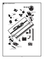
Page 17: ...Board 041B5351 5 Light Socket 041C5392 Block Terminal 041B4375 3 Belt 031D0537 Chain 031D0525 Belt Pulley 041A5845 Transformer 041C5350 5 MT600 041C5350 7 MT1000 026B0072 Power Cord If the supply cor...

Page 18: ...orce or down limit 10 Door opens but won t close Check The Protector System if you have installed this accessory If the light is blinking correct alignment If opener light does not blink and it is a n...

Page 19: ...roken by an obstruction causes a closing door to open and prevents an open door from closing It is STRONGLY RECOMMENDED for homeowners with young children Allow a 15 minute cooling period after 5 cont...

Page 20: ...urchase from the Seller The MT600 MT1000 motor is covered by an additional 5 years from date of purchase if used on a domestic door Please retain your proof of purchase in the unlikely event you requi...

Reviews: