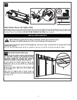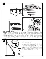
Once a Year:
• Apply grease to rail and trolley
• Oil door rollers, bearings and hinges
• DO NOT lubricate the opener itself
• DO NOT APPLY grease to the door tracks
When properly installed, opener will provide high performance with
a minimum of maintenance. The opener does not require additional
lubrication.
Limit and Force Settings: These settings must be checked and
properly set when opener is installed. Weather conditions may cause
some minor changes in the door operation, requiring some
re-adjustments, particularly during the first year of operation
.
Refer to
Setting the Limits and Force on page 5. Follow the instructions
carefully and repeat the safety reverse test after any adjustment.
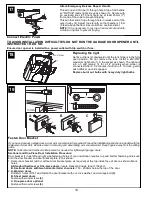
Remote Control: The remote control may be secured to a car sun visor
with the clip provided. Additional remotes can be purchased at any time
for use in all vehicles using garage. Refer to Accessories. Any new
remotes must be programmed into the opener.
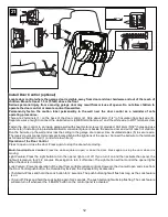
Remote Control Battery: The lithium batteries should produce power
for up to 5 years. If transmission range decreases, replace battery.
To Change Battery: To replace batteries, use the visor clip or
screwdriver blade to pry open the case. Insert batteries
positive side up.
To replace cover, snap shut along both sides. Do not dispose of the old
battery with household waste. Take batteries to a proper disposal center.
MAINTENANCE OF YOUR OPENER
CARE OF YOUR OPENER
OPERATION OF YOUR OPENER
Your opener can be activated by any of the following devices:
• The Backlit Door Control Button. (If Installed). Hold the button
down until door starts to move.
• The Outside Keylock or Keyless Entry System (if you have installed
either of these accessories).
• The Remote Control Transmitter. Hold the push button down until
the door starts to move.
Opening the Door Manually:
Door should be fully closed if possible. Weak or broken springs
could allow an open door to fall rapidly. Property damage or
serious personal injury could result.
The door can be opened manually by pulling the release handle down
and back (toward the opener). To reconnect the door, pull the release
handle straight down.
Do not use the manual release handle to pull the door opener
or closed.
When the Opener is Activated by Remote Control or Backlit Door
Control Button:
1. If open, the door will close. If closed, the door will open.
2. If closing, the door will stop.
3. If opening, the door will stop (allowing space for entry and exit of pets
and for fresh air).
4. If the door has been stopped in a partially open or closed position, it
will reverse direction.
5. If an obstruction is encountered while closing, the door will reverse.
6. If an obstruction is encountered while opening, the door will reverse,
then stop.
7. The optional Protector System™ uses an invisible beam which, when
broken by an obstruction, causes a closing door to open and prevents
an open door from closing. It is STRONGLY RECOMMENDED for
homeowners with young children.
Allow a 15 minute cooling period after 5 continuous operations
of the opener.
The opener light will turn on: 1. when opener is initially plugged in;
2. when the power is briefly interrupted; 3. when the opener is activated.
The light turns off automatically after 2-1/2 minutes. Bulb size is
24V/21W maximum.
Input Voltage...................230-240 VAC, 50Hz
Max. Pull Force ..............600N
Power .............................115W
Standby Power ...............5.5W
Normal Torque ................5Nm
Motor
Type ................................DC gearmotor permanent lubrication
Drive Mechanism
Drive ...............................Chain with two-piece trolley on
steel rail.
Length of Travel..............Adjustable to 2.3m
Travel Rate .....................127-178mm per second
Lamp...............................On when door starts, off 2-1/2 minutes
after stop.
Door Linkage ..................Adjustable door arm. Pull cord trolley release.
Safety
Personal .........................Push button stop in UP and DOWN
direction. Automatic stop in UP and DOWN
direction.
Electronic ........................Automatic force adjustment
Electrical .........................Transformer overload protector and low
voltage push button wiring.
Limit Device ....................Optical RPM/Passpoint detector.
Limit Adjustment .............Electronic, Semi and Fully Automatic.
Start Circuit.....................Low voltage push button circuit.
Dimensions
Length (Overall)..............3.2m
Headroom Required .......30mm
Hanging Weight ..............16kg
Receiver
Memory Registers ..........12
Operating Frequency......433.92MHz
SPECIAL NOTE: Chamberlain strongly recommends that the protector
system be installed on all garage door openers.
SPECIFICATIONS
21

