background image

Intended use

The device is intended for the opening and closing of tilt-up and 
sectional garage doors in the private sector. The device is not meant
for commercial use but solely for the use in private garage doors that
are appropriate for a single household.
Any improper use of the drive could increase the risk of accidents. 
The manufacturer assumes no liability for such usage.

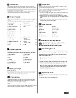
Scope of supply

Please check the supplied parts for completeness before starting the in-
stallation. 
Note: The numbering only applies to the corresponding section. 

Product overview

This figure always offers you a complete overview of the ready-
assembled system during the step by step installation of the system.

Before you begin

IMPORTANT NOTE
If your garage does not have a side entrance, an external emergency
release should be installed. This allows for manual operation of the
garage door from the outside during power failure.

Preconditions

The garage door opener is suitable only for installation in one-piece
garage doors with horizontal guide rail (tilt-up door) (Fig. A) and in 
sectional doors with curved guide rail (Fig. B).

NOTE: 
The system cannot be used for one-piece garage doors with horizontal
and vertical guide rails and two-wing doors or overhead doors.

Preparation

First, check whether your door is balanced and in equilibrium. Open
your door about halfway and let it go.
The door can now hardly change its position 

independently,

but must

remain in this position held by the spring force alone.
Motive force: maximum 15 kg.

1. The rail of the garage door MUST be connected securely and firmly

to the supporting wall or ceiling above the garage door.

2. Additional brackets and mounting rails (not included in the supply)

might be required, if the your garage ceiling has a cladding, boards or
similar.

3. If your garage does not have a separate side entrance, an external

emergency release should be installed.

Tools required

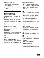
Assembly of the door opener

Important instructions for a safe installation. 
Observe all assembly instructions.

Incorrect installation can cause serious injury.

Assembling the rail

The rail is largely preassembled and consists of 

4

 parts. The carriage,


push rod, release handle, the guide pulley and the lintel bracket with
chain tensioner are in the front part (A). The seating for the drive shaft
and the sprocket are in the rear part (B). Lay the front and rear rail 
sections one behind the other.

1.

Remove cable ties that secure the chain. Leave the transport lock

(X)

still in position.

2.

Pull apart the two rail sections completely in order to create a gap
for the middle section

s

 (C

 & D

). This rail is designed in such a way

so as


to easily add the middle section

s

. Slide the connecting

pieces (

E

)


over the seams of the rail sections up to the markings.

To secure


the connecting pieces, bend the sheet metal lugs out-

wards with a


suitable tool.

The assembly of the rail is complete.

Tighten the chain

Tighten the chain of the rail until the spring (1) is compressed only by
about half. 

This must be able to bounce during operation.

2

5.2

5.3

6

6.1

6.2

3

4

5

5.1

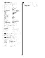
Parts overview:

1. Drive head

1x

2. Handheld transmitter

2x

3. Curved door arm

1x

4. Support bracket

2x

5. Mounting bracket

3x

6. Header bracket

1x

7. Door fixture

1x

8. Accessories bag 

1x

9. Rail

1x

Hardwarebag:

1. Truss head screw

6 x 80 mm

1x

2. Lock nut M6

1x

3. Hexagonal head screw

4x

4. Nut M6

4x

5. Bolt

1x

6. Safety cotter pin

1x

7. Screw

ST6 x 50 mm

4x 

8. Screw

ST6,3 x 18 mm

8x

9. Plug

4x

1. Header bracket

2. Chain

3. Rail

4. Carriage

5. Connecting piece

6. Mounting bracket

7. Support bracket

8. Power cable

9. Drive head

10. Release

11. Straight door arm

12. Curved door arm

13. Door bracket

Tool list:

Ladder

Marking pen

Pliers

Drilling machine

Hammer

Ratchet

 (10, 13 mm)

Hacksaw

Different drill bits 
(8, 6, 5, 4.5 mm)

Box wrench

Water level

Screwdriver

Measuring tape

en 03/09

Summary of Contents for ML550EV

Page 1: ...perating instructions for Garage Door Opener ML550EV Notice de montage et de commande pour entra nements de portes de garage ML550EV Montage en bedieningshandleiding voor garagepoortaandrijvingen ML55...

Page 2: ...entorantrieb aufh ngen 4 7 5 Torbefestigung montieren 4 7 6 Schubstange am Laufwagen befestigen 5 8 Elektroanschluss 5 8 1 Optionales Zubeh r 5 8 2 Garagentorantriebseinheit anschlie en 5 9 Tor einste...

Page 3: ...ert werden Beim Betrieb darf das Tor unter keinen Umst nden ffentliche Durchgangswege behindern Um allen Bedienern die sichere Bedienung in Erinnerung zu rufen ist neben dem beleuchteten Wandtaster da...

Page 4: ...ge ber keinen separaten Seiteneingang verf gt muss eine externe Notentriegelung installiert werden Ben tigtes Werkzeug Montage des Garagentorantriebs Wichtige Anweisungen f r sichere Montage Alle Mont...

Page 5: ...t abgest tzt Leiter oder von einer zweiten Person festgehalten werden Garagentorantriebskopf auf Garagenboden unter die Sturzbefestigung legen Schiene anheben bis die L cher des Befestigungsteils und...

Page 6: ...ie Funktion leichter Lauf berpr ft werden Der Garagentorantrieb ist kein Hilfsmittel f r ein schlecht funktionieren des Tor Kontrollieren Sie die einwandfreie Funktion des Tores vor jeder nderung der...

Page 7: ...nen auf ein Hindernis trifft Lichtschranke optional Mittels einer Lichtschranke wird ein sich schlie endes Tor hochgefahren bzw ein offenes Tor am Schlie en gehindert wenn eine im Torbereich befindlic...

Page 8: ...g H ufig gestellte Fragen 1 Garagentoranrieb l sst sich mit Handsender nicht anschalten Ist der Garagentorantrieb an die Stromversorgung angeschlossen Schaltet sich eine an die Steckdose angeschlossen...

Page 9: ...e w hrend der Fahrt ist ein Zeichen f r ein nicht gleichm ig funktionierendes Tor mit stetig wechselnden Kraftbedarf Fachmann rufen evtl Tor schmieren Eine zus tzliche Abh ngung an der Schiene kann Ab...

Page 10: ...optional 1 TX4RUNI 2 128REV 3 747REV 4 75REV 5 771REV 4 Kanal Handsender 2 Kanal Funk Wandtaster Funkcodeschloss beleuchteter Wandtaster Sicherheitslichtschranke Das Tor reversiert automatisch ohne da...

Page 11: ...opener 4 17 5 Mounting door bracket 4 17 6 Attaching door arm on the trolley 5 18 Electrical connection 5 18 1 Optional Accessories 5 18 2 Connecting the opener 5 19 Program opener and test 5 19 1 Adj...

Page 12: ...wet areas During operation the gate should not under any circumstances obstruct public passageways To remind all operators of the safe operation in addition to the illuminated wall switch a warning si...

Page 13: ...oes not have a separate side entrance an external emergency release should be installed Tools required Assembly of the door opener Important instructions for a safe installation Observe all assembly i...

Page 14: ...rson Put drive head on garage floor under the lintel bracket Lift rail up till the holes of the fixing part and the holes of the lintel bracket are aligned Insert screw 1 through the holes and secure...

Page 15: ...e adjustment check the door for proper functioning The opener is no support for a malfunctioning door You can check proper functioning by releasing the opener and opening and closing the door manually...

Page 16: ...ters an obstacle during opening Light barrier optional By means of the light barrier a closing door is lifted up or an open door is obstructed while closing if a person lo cated in the door area inter...

Page 17: ...ol Is the opener connected to the power supply If a lamp connected to the power socket does not turn on check fuse or circuit breaker Some sockets are enabled via a wall switch Are all door locks disa...

Page 18: ...pension on the rail can be a remedy 15 The opener runs audible turning of motor but the carriage does not move The carriage is released from the opener In a new installation During the assembly of mot...

Page 19: ...s Operating frequency 433 MHz 868 MHz Battery 3 V type CR2032 10A20 WH Spare parts Warranty Please refer to www chamberlain eu or contact your local dealer Also refer to the available Warranty Book Ac...

Page 20: ...5 Montage de la fixation de la porte 4 17 6 Fixation du bras de porte au chariot 5 18 Branchement lectrique 5 18 1 Accessoires en option 5 18 2 Branchement d entra nement 5 19 R glage et essai de la...

Page 21: ...utilisation la porte ne doit en aucun cas g ner les voies de circulation publiques Pour rappeler tous les utilisateurs la manipulation en toute s curit le panneau d avertissement pour la protection de...

Page 22: ...ne entr e lat rale un syst me de d verrouillage de secours externe doit tre install Outils n cessaires Montage de l entra nement de porte Consignes importantes pour un montage s r Respecter toutes les...

Page 23: ...me personne Posez la t te d entra nement sur le sol du garage sous la fixation de linteau Soulevez le rail jusqu ce que les trous de la partie fixer et les trous de la fixation de linteau corresponde...

Page 24: ...ant chaque modification du r glage de la force la porte doit tre con tr l e quant son parfait fonctionnement facilit de mouvement L en tra nement n est pas un moyen auxiliaire pour une porte qui fonct...

Page 25: ...lors de l ouverture barri re photo lectrique option Gr ce une barri re photo lectrique une porte en train de se fermer se rouvre ou la fermeture d une porte ouverte est emp ch e si une personne se tro...

Page 26: ...limination Questions fr quentes 1 L entra nement de porte ne peut pas tre actionn avec la t l commande L entra nement est il branch l alimentation lectrique Si une lampe branch e sur la prise ne s al...

Page 27: ...ra nement fl chit La porte est tr s lourde tr s lourde fonctionne difficilement ou est en mauvais tat Appelez un sp cialiste Les vibrations du rail pendant la course indiquent un fonctionnement irr gu...

Page 28: ...suspendu 10 kg R cepteur radio M moire 16 t l commandes Fr quence de service 433 MHz 868 MHz Pile 3 V type CR2032 10A20 WH Pi ces d tach es Garantie Reportez vous www chamberlain eu ou contactez votr...

Page 29: ...phangen 4 17 5 Poortbevestiging monteren 4 17 6 Poortarm op de loopwagen bevestigen 5 18 Elektrische aansluiting 5 18 1 Optioneele toebehoren 5 18 2 Aandrijfeenheid aansluiten 5 19 Poort instellen en...

Page 30: ...bedrijf mag de poort in geen enkel geval openbare doorgangswegen belemmeren Om alle bedieningspersonen te herinneren aan de veilige bedieningswijze moet naast de verlichte drukknop het waarschuwingsbo...

Page 31: ...terne noodontgrendeling worden ge nstalleerd Benodigde gereedschappen Montage van de poortaandrijving Belangrijke aanwijzingen voor een veilige montage Alle montageaanwijzingen volgen Verkeerde montag...

Page 32: ...der of door een tweede persoon worden vastgehouden Aandrijfkop op garagevloer onder de lateibevestiging leggen Rail optillen tot de gaten van het bevestigingsstuk of de gaten van de lateibevestiging o...

Page 33: ...een onberispelijke werking vlotte loop worden gecontroleerd De aandrijving is geen hulpmiddel voor een slecht functionerende poort Controleer voor elke wijziging van de aandrijvingsinstellingen of de...

Page 34: ...is dan keert de poort terug in de open positie wanneer ze bij het sluite nop een hindernis stoot dan stopt de poort wanneer ze bij het openen op een hindernis botst Foto elektrische beveiliging optio...

Page 35: ...act aangesloten lamp niet ingeschakeld controleer dan de overbelastingsschakelaar sommige stopcontacten worden via een wandschakelaar ingeschakeld Zijn alle poortblokkeringen uitgeschakeld Zie veiligh...

Page 36: ...e Raadpleeg een specialist en smeer evt de poort Een bijkomende ophanging aan de rail kan het probleem verhelpen 15 De aandrijving werkt motor draait hoorbaar maar de loopwagen beweegt niet De loopwag...

Page 37: ...RUNI 2 128REV 3 747REV 4 75REV 5 771REV Handzender 2 kanaals Draadloze Drukknop 2 kanaals Sleutelloos bedieningssysteem Deurbediening Foto elektrische beveiliging keert de poort automatisch om zonder...

Page 38: ...Zav en pohonu vrat 4 17 5 Mont chytu vrat 4 17 6 Upevn n ramene vrat k pojezdu 5 18 Elektrick p pojka 5 18 1 Voliteln p slu enstv 5 18 2 P ipojen hnac jednotky 5 19 Nastaven a vyzkou en vrat 5 19 1 Na...

Page 39: ...k ch nebo mokr ch prostor ch P i provozu nesm vrata za dn ch okolnost omezovat cesty pro pr chod ve ejnosti Aby v echny osoby m ly bezpe n ovl d n neust le na pam ti je t eba vedle osv tlen ho n st nn...

Page 40: ...y 3 Jestli e Va e gar nem samostatn bo n vchod je nutn instalovat extern nouzov odblokov n Pot ebn n stroje Mont pohonu vrat D le it pokyny pro bezpe nou mont Dodr ujte v echny mont n pokyny N sledkem...

Page 41: ...od horn chyt Kolejnici nadzvedn te tak aby otvory upev ovac ho d lu a otvory horn ho chytu le ely nad sebou roub 1 prot hn te otvory a zajist te matic Zav en pohonu vrat 1 Vrata pln otev ete pohon vra...

Page 42: ...patn fungov n vrat Kontrolujte bezchybnou funkci vrat p ed ka dou zm nou nastaven pohonu tak e vrata odblokujete od pohonu a rukou je otev ete a zav ete Vyzkou en automatick ho bezpe nostn ho zp tn h...

Page 43: ...e naposledy vykon van pohyb kdy jsou ste n otev ena vrata zajedou zp tky do otev en polohy kdy p i zav r n naraz na p ek ku vrata se zastav kdy p i otev r n naraz na p ek ku sv teln z vora voliteln Po...

Page 44: ...t en N kter z suvky se zap naj n st nn m sp na em Jsou v echny z mky vrat deaktivov ny Viz bezpe nostn pokyny Mus sv tit kontroln dioda LED na d lkov m ovlada i kdy se tla tko stiskne Jinak je bu to p...

Page 45: ...se m n c m p konem Zavolejte odborn ka p p vrata nama te Pomoci m e dal z v s na kolejnici 15 Pohon b motor se sly iteln ot ale pojezd se nepohybuje Pojezd je odblokov n od pohonu U nov instalace P i...

Page 46: ...1 2 3 0 2 R C p y T V 3 e i r e t a B N hradn s ly Z ruka Viz na www chamberlain eu nebo se obra te na va eho prodejce Viz tak v z ru n kn ce dod van s p strojem P slu enstv voliteln 1 TX4RUNI 2 128RE...

Page 47: ......

Page 48: ...114A4C086 2016 all rights reserved Chamberlain Germany Alfred Nobel Strasse 4 D 66793 Saarwellingen www chamberlain eu diy chamberlain eu...

Page 49: ...s BASIC ML510EV tmotat k BASIC ML510EV Ohjeet BASIC ML510EV Obr zky BASIC ML510EV BASIC ML510EV Upute BASIC ML510EV BASIC ML510EV en de A B B 2 1 1 A B C D D ca 36 38 mm 1 3 4 5 2 4x 2x X 1 2 1 2 min...

Page 50: ...7 4 1 2 7 3 S P 1 2 3 S P 1 2 3 S P 1 2 3 S P 1 2 3 S P 1 2 3 2 3 2 1 2 3 2 1 2 3 2 1 2 3 2 1 2 3 2 1 2 3 4 5 6 P S 1 3 2 3 2 2 1 P S 1 3 2 3 2 2 1 1 S P 1 2 3 2 3 2 1 7 5 C1 C2 C3 10 8 1 4 2 3 1 WHT...

Page 51: ...att den nedan betecknade produkten av typen Garageportsdrivenhet ML510EV uppfyller de grundl ggande kraven i f ljande EG direktiv om den anv nds som avsett enligt tillverkarens anvisningar I synnerhet...

Page 52: ...t bijzonder werden de volgende geharmoniseerde normen toegepast Seriennummer Serial number le num ro de s rie po adov slo Seriennummer 2006 42 EG Maschinenrichtlinie Machinery Directive Directive Mach...

Reviews: