GB-6
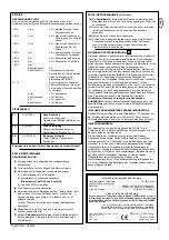
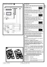
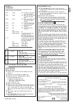
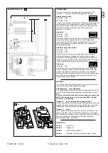
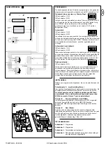
CONNECTIONS PLAN
NC
NC
24V~
24V~
24V~
24V~
2
Optional
2
3
Optional
3
2B2
2B
2B
2B2
STOP
OPEN
CLOSE
Partial
opening
Total
opening
LED signalling
the gate position
K
A
2S
NC
NO
SC1 ( )
9
4S
OPTIONAL
11
2
3
4
1
2
3
44
1
2
1
2
+ -
NC C NO
+ -
PROGRAMMES
The control unit offers 4 operating modes (programmes). DIP
switches 1 + 2 are used to select the programme required.
Default (step-by-step):
DIP switch 1 OFF
DIP switch 2 ON
The gate does not close automatically. Trimmer (potentiometer) B is
non-functioning. The infrared sensor reverses the gate to OPEN
when the latter closes. Should the infrared sensor also need to be
active when the gate is opening, it has to be connected to
contact 11 + 12 (stop).
Automatic:
DIP switch 1 OFF
DIP switch 2 OFF
Once it has opened fully, the gate then closes automatically after the
set time has elapsed (pause, trimmer B). The infrared sensor
reverses the gate to OPEN when the latter closes. If the infrared
sensor is interrupted in a gate open position, the set pause is
automatically extended.
Automatic (rapid close mode):
DIP switch 1 ON
DIP switch 2 OFF
Should the control unit receive a pulse signal from a handset or
switch when the gate is opening, the latter will then be closed
immediately. If the infrared sensor is interrupted while the gate is
waiting in an open position, the set pause is reduced and the gate is
closed immediately (otherwise as automatic mode).
Dead man:
DIP switch 4 ON
A signal has to be sent constantly to the control unit via the key
switch or handset in order to operate the gate in this mode. If the
signal is interrupted, the gate stops and moves in the opposite
direction when the next signal is received. This mode should always
be selected when the gate has not been properly secured or the
infrared sensor is out of action.
SETTINGS
Once you have decided which programme you want to select, you
then need to set the potentiometer accordingly.
Potentiometer A
force adjustment
This setting defines the force with which the motor should work. The
force needed depends on the weight and functionality of the given
gate.
The force measured at the gate's closing edge may not exceed
400N. If the closing force is set to more than 400N, the light
barrier has to be installed.
Trimmer B
pause (waiting time in open position)
Should the automatic or automatic with STOP programme have been
selected, the gate's waiting time must be defined when it is in gate
OPEN mode. Once the set time has elapsed, the gate closes.
Trimmer C
brake
When the gate reaches its limit switch, the drive switches off. The
gate's momentum carries it a little further depending on its weight
and functionality. The brake function can be set to actively brake the
gate and minimise any undesirable further travel. Maximum
anticlockwise setting = brake OFF.
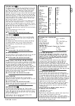
DIP SWITCH
Switch 1
Programme
Switch 2
Programme
Switch 3
Speed sensor (optional)
Switch 4
Dead man (drive runs as long as signal is sent)
9
9 A
709207B-GB - 05.2004
© Chamberlain GmbH, 2004


