en-6
JUMPERS
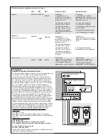
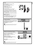
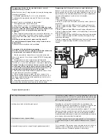
Programming of failsafe photocells model 771EML
1.Before the Initial Setup
2.When connecting or removing photocell(s)
- Switch off control board ( disconnect from current)
- Slip jumper on designated pins
- Dipswitch 5 to “ON”
- Connect photocell(s) according illustration
- Reconnect control board, wait short-time
- Pull jumper, wait short-time
Done! (The number of photocells connected are stored)
Programming of relay photocells such as 263EML
The control board must be disconnected from the mains for a few
seconds. All terminals to which no photocell is connected must be
bridged with COM. (21-24, 22-24, 23-24). The power supply for the
relay photocell of terminals 15-16. Dip switch 5 must be at OFF. The
jumper must be unplugged.
Note: Relay photocells are no longer permitted for new installations
as per EN12978, because they cannot perform self-checks (failsafe).
Operation without photocells
DANGER:
Not permitted for normal operation. In this case contact
strips must safeguard the gate.
The control board must be disconnected from the mains for a few
seconds. Terminals 21-22-23-24 must all be bridged. Dip switch 5
must be at OFF. The jumper must be unplugged.
Note: It is not possible to combine different photocell models.
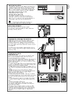
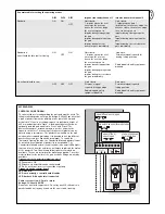
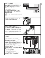
FLASHING LAMP (OPTIONAL)
A flashing lamp can be connected to the control board. It warns when
the gate is being moved. The flashing light should be fitted as high as
possible and in good clear view. The control board emits a constant
signal that the lamp converts to a flashing signal.
Cable cross-section: 0.5 mm
2
or more.
Voltage: 24 V DC
Do not use any fixed copper lines. Do not lay any 230 volt
cables in parallel and do not lay any 2 cables in the same cable
trunking.
34EML
41EML
PUSHBUTTON / KEY-OPERATED SWITCH (OPTIONAL)
The control board / drive can be activated using various inputs. This
can be done using a transmitter or keyswitch (terminals 17 and 20).
Transmitter = see “Teaching the transmitter”
Switch input 1 = input control 1 normal operation
Switch input 2 = input control 2 active for special settings
(see Dip switch description)
EMERGENCY STOP (OPTIONAL)
A switch can be connected to stop or disable the unit. The
movement of the wings is stopped immediately. Terminals 19 and
20 must be bridged if no switch is installed.
24 VDC - OUTPUT
For relay infrared senors or other devices (e.g. receivers)
max. 500 mA
Do not use any fixed copper lines. Do not lay any 230 volt
cables in parallel and do not lay any 2 cables in the same cable
trunking.
Summary of Contents for MotorLift HC600
Page 17: ...115o 90o 90o 90o 115o 115o 115o 90o 1 2 3...
Page 18: ...A 38 5cm 8 5cm 30cm 7 8cm 90 max 10cm C B 60 70cm 4 5 A B 6 7 8...
Page 19: ...9 11 12 10...
Page 22: ......


