background image

it-5

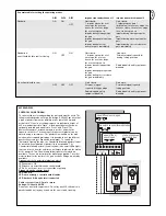
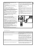
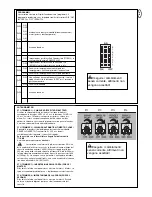
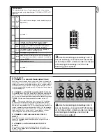
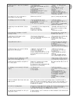
Tabella separata per l’impostazione delle modalità di funzionamento

Cancello chiuso:
1. impulso apre, il seguente
arresta, il successivo chiude,
quello dopo arresta, il
prossimo apre, ecc.

Cancello chiuso:
1. impulso apre battente 1(per
pedoni), il seguente arresta, il
successivo chiude, quello dopo
arresta, il prossimo apre, ecc.

Impulso in fase di chiusura
blocca il cancello

Impulso in fase di chiusura
blocca il cancello

Impulso in fase di apertura
blocca il cancello

Impulso in fase di apertura blocca
il cancello

Impulso in fase di pausa
chiude immediatamente il
cancello

Impulso in fase di pausa chiude
immediatamente il cancello

Modalità standard

Modalità standard &
di nessun arresto automatico (uomo

presente) in fase di chiusura

Cancello chiuso:
1. impulso apre, il seguente
arresta, il successivo chiude,
quello dopo arresta, il
prossimo apre, ecc.

Cancello aperto:
Tenere premuto per chiusura,
rilasciare per arresto

Impulso in fase di chiusura
blocca il cancello

Radiosegnale disattivato, dispositivi
di sicurezza disattivati

Impulso in fase di apertura
blocca il cancello

Impulso in fase di pausa
chiude immediatamente il
cancello

DIP1

ON

ON

OFF

DIP2

ON

OFF

OFF

DIP3

OFF

ON

OFF

Generatore di impulsi/canale 1

Generatore di impulsi/canale 2

Nessun arresto automatico (uomo
presente)

Cancello chiuso:
tenere premuto,
rilasciare per arresto

Cancello aperto:
tenere premuto,
rilasciare per arresto

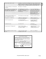
Radiosegnale disattivato,
dispositivi di sicurezza
disattivati

Radiosegnale disattivato,
dispositivi di sicurezza disattivati

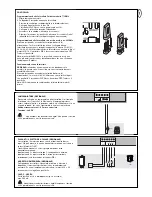
ACCESSORI

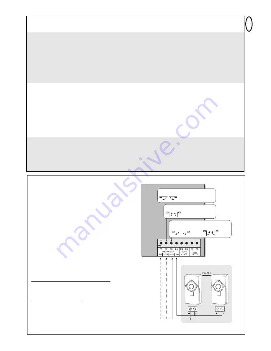
FOTOCELLULE (OPZIONALI)

Le fotocellule servono per rendere sicuro il cancello e devono essere
sempre installate. La posizione di montaggio dipende dal modello del
cancello. Ai sensi della EN12453, una coppia di fotocellule deve
essere installata esternamente ad un’altezza di 200 mm, con
modalità attiva in fase di chiusura; un’altra coppia di fotocellule deve
essere installata internamente ad un’altezza di 200 mm, con modalità
attiva in fase di apertura. Un terzo paio di fotocellule, con modalità
attiva in fase di chiusura e apertura, può essere installata
facoltativamente. Le fotocellule sono composte da un trasmettitore e
da un componente di ricezione e devono essere poste l’una di fronte
all’altra. L’alloggiamento per le fotocellule (plastica) può essere aperto
con l’ausilio di un cacciavite. La fotocellula viene fissata al muro
tramite piccole viti e tasselli. È possibile azionare due sistemi di
fotocellule diversi (ved. descrizione interruttori DIP). Se si vuole
ammettere la funzione “chiusura automatica”, è necessario installare
la fotocellula Failsafe Chamberlain. Non è possibile utilizzare una
combinazione di fotocellule. Il sistema Failsafe Chamberlain (sistema
a 2 cavi) è dotato, su entrambe le estremità, di un piccolo LED (luce)
visibile da fuori, che mostra lo stato della fotocellula. Esistono due
modelli di fotocellule Failsafe Chamberlain. La prima variante è ideale
per essere montata su pareti che si fronteggiano. La seconda è
ideale per essere montata nella parte interna del cancello, dato che
contiene già le guarnizioni per il montaggio. 
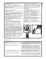
Segnali luminosi sulla fotocellula Failsafe Chamberlain
LED fisso = OK
LED lampeggiante = la fotecellula blocca la centralina
LED spento = mancanza di corrente, collegamento errato o poli
invertiti

Segnali luminosi sulla centralina
LED spento = OK
LED fisso = centralina bloccata
LED lampeggiante = OK, nessuna fotocellula collegata

Sezione trasversale cavi: 0,5 mm

2

o superiore.

Tensione: 12/24 Volt AC/DC.

Non utilizzare conduttori di rame rigidi. Non posare i cavi da 230 V
parallelamente o nello stesso cunicolo.

open/öffnen/ouvrir/open

close/schliessen/fermer/sluiten

close/schliessen/

fermer/sluiten

open/öffnen/

ouvrir/open

771EML

Summary of Contents for MotorLift HC600

Page 1: ...0 Installazione mecaniche HC600 Mechanische Installatie HC600 TM TM Voor Service 31 0 20 684 7978 nl F r Service 49 0 6838 907 100 Pour Service 33 0 3 87 95 39 28 For Service 0800 317847 de fr en Per...

Page 2: ...ie Anlage darf nicht benutzt werden wenn Reparatur oder Einstellarbeiten durchgef hrt werden m ssen Diese Anlage darf nicht von Personen bedient werden einschliesslich Kindern die k rperlich oder geis...

Page 3: ...ur ckdrehen Abb 11 MONTAGE DES DREHTORANTRIEBS 1 Montieren Sie die Arme am Motor Abbildung 5 Entriegeln Sie den Antrieb mit dem mitgelieferten Entriegelungsschl ssel Sechskantschl ssel durch drehen Ab...

Page 4: ...rung 3 Lichtschranke aktiv in Schlie en H he max 200mm Erste Lichtschranke 4 Lichtschranke aktiv in ffnen H he max 200mm Zweite Lichtschranke 5 Blinkleuchte Optional Wichtiger optischer Hinweis auf di...

Page 5: ...es leurs facult s physiques ou mentales ou qui n ont pas suffisamment d exp rience en mati re d utilisation de l installation dans la mesure o elles ne sont pas surveill es ou n ont pas t form es l ut...

Page 6: ...iron 180 degr s jusqu en but e L entra nement est alors d verrouill Pour le reverrouiller ramener la cl en position initiale fig 11 MONTAGE 1 Montez les bras sur le moteur fig 5 D verrouillez l automa...

Page 7: ...ds max portail 250kg CONFIGURATION TYPIQUE D UNE INSTALLATION 1 Moteur 2 Commande 3 Barri re photo lectrique active en fermeture hauteur max 200 mm Premi re barri re photo lectrique 4 Barri re photo l...

Page 8: ...their safety This safety alert symbol means Caution failure to comply with such an instruction involves risk of personal injury or damage to property Please read these warnings carefully This gate dr...

Page 9: ...INSTALLATION OF THE UNIT 1 Mount the arms on the motor Fig 5 Switch to manual operation by inserting and turning the hexagonal key provided Fig 11 2 Select and mark the mounting height on the pier Fig...

Page 10: ...odel ANT4X EML Antenna TYPICAL CONFIGURATION OF A UNIT 1 Motor 2 Control board 3 photocell active for closing max height 200 mm First photocell 4 photocell active for opening max height 200 mm Second...

Page 11: ...pianto non deve essere usato da persone inclusi i bambini con handicap fisici o mentali n da persone carenti di esperienza per quanto riguarda l utilizzo dell impianto a meno che le stesse non agiscan...

Page 12: ...Sbloccare l attuatore ruotando la chiave di sblocco fornita in dotazione chiave esagonale figura 11 2 Scegliere e segnare l altezza di montaggio sul pilastro figura 4 5 3 Il cancello deve essere molto...

Page 13: ...IO TIPICO DI UMN IMPIANTO 1 Motore 2 Centralina 3 Fotocellula attiva in fase di chiusura altezza max 200mm Prima fotocellula 4 Fotocellula attiva in fase di apertura altezza max 200mm Seconda fotocell...

Page 14: ...ig op tekenen van slijtage of beschadiging worden gecontroleerd De installatie mag niet worden gebruikt wanneer reparatie of onderhoudswerkzaamheden moeten worden uitgevoerd Deze installatie mag niet...

Page 15: ...1 Bevestig de arm aan de motor afbeelding 5 Ontgrendel de aandrijving door aan de bijgeleverde sleutel zeskantsleutel te draaien afbeelding 11 2 Kies en markeer de montagehoogte op de pilaar afbeeldin...

Page 16: ...2 Besturing 3 Fotocelbeveiliging actief sluiten hoogte max 200 mm Eerste fotocelbeveiliging 4 Fotocelbeveiliging actief openen hoogte max 200 mm Tweede fotocelbeveiliging 5 Knipperlicht optioneel Bela...

Page 17: ...115o 90o 90o 90o 115o 115o 115o 90o 1 2 3...

Page 18: ...A 38 5cm 8 5cm 30cm 7 8cm 90 max 10cm C B 60 70cm 4 5 A B 6 7 8...

Page 19: ...9 11 12 10...

Page 20: ...709431E 041ASLC 0120 041AART 0013 041AART 0011 041AART 0012 ART 3AL 041AART 1022SA 041AART 1023SA 13...

Page 21: ...rische installatie HC280ML HC300ML MLS HC400ML MLS HC600ML MLS Instrucciones y instalaci n el ctrica HC280ML HC300ML MLS HC400ML MLS HC600ML MLS Manuais e instala o el ctrica HC280ML HC300ML MLS HC400...

Page 22: ......
Page 23: ...Totmann Max Laufzeit 80 sec Pause Zeit 0 150sec Abmessungen 124x152mm Ohne Box BEGINNEN SIE MIT LESEN DIESER WICHTIGEN SICHERHEITSREGELN Solche Warnzeichen bedeuten Vorsicht eine Aufforderung zur Bea...

Page 24: ...mit dem Schwarzen Kabel getauscht werden Vorher ist die Stromzufuhr zu unterbrechen Typischer Aufbau einer Anlage 1 Motor 2 Steuerung 3 Lichtschranke aktiv in Schlie en H he max 200mm Erste Lichtschr...

Page 25: ...anal 2 9 L1 Drucktaster Einlernen Wegstrecke 10 JMP1 Steckbr cke Lichtschrankenprogrammierung 11 DIP1 Dip Schalter Block 12 PT4 Potentiometer Krafteinstellung Antrieb 2 13 PT3 Potentiometer Krafteinst...

Page 26: ...ksanschlag Fl gelverz gerung AUS PT2 Trimmer 2 Automatisches Schlie en Timer to close Die Wartezeit des Tores in TOR AUF kann definiert werden 0 150 sec nachdem die eingestellte Zeit abgelaufen ist wi...

Page 27: ...in Schliessen installiert werden ein zweites Paar innen in einer H he von 200mm aktiv in ffnen Ein drittes Paar Lichtschranken aktiv in Schliessen und ffnen kann optional installiert werden Die Licht...

Page 28: ...gen werden Hinweis Lichtschranken unterschiedlicher Bauart k nnen NICHT kombiniert werden BLINKLAMPE OPTIONAL Eine Blinkleuchte kann an die Steuerung angeschlossen werden Sie warnt Personen vor dem si...

Page 29: ...ne parallele Verlegung von Kabeln mit 230Volt oder der Verlegung im gleichen Kabelkanal 600046EML 600060EML ERSTE INBETRIEBNAHME GRUNDEINSTELLUNG Gehen Sie Punkt f r Punkt genau durch Beginnen Sie im...

Page 30: ...mit dem Tor haben wie die Bewegungen des Tores ablaufen wie die Sicherheitsfunktionen arbeiten und wie der Antrieb von Hand bet tigt werden kann de 8 H ufig gestellte Fragen Wie hoch ist die voraussi...

Page 31: ...finden und beheben Automatisch Schlie en funktioniert nicht 1 Funktioniert nur mit der 2 Kabel Lichtschranke 770E ML oder 771E ML 2 Dann Potentiometer f r Automatisch Schlie en im Uhrzeigersinn drehen...

Page 32: ...tallation einer Aussenantenne ist empfehlenswert da sich die Steuerung mit der kurzen Kabelantenne in den meisten F llen hinter dem Pfeiler oder in Bodenn he befindet Die optimale Antennenposition ist...

Page 33: ...ce Standard Standard Homme mort contact maintenu en fermeture Homme mort contact maintenu Dur e de course max 80 sec Dur e pause 0 150 sec Dimensions 124x152 mm sans bo tier VEUILLEZ TOUT D ABORD LIRE...

Page 34: ...du des moteur sdoivent tre intervertis sur la commande Il faut d abord couper l arriv e du courant Configuration typique d une installation 1 Moteur 2 Commande 3 Barri re photo lectrique active en fer...

Page 35: ...r course 10 JMP1 cavalier Programmation de barri re photo lectrique 11 DIP1 Bloc commutateurs DIP 12 PT4 potentiom tre R glage de force entra nement 2 13 PT3 potentiom tre R glage de force entra nemen...

Page 36: ...ation des battants inactive PT2 POTENTIOM TRE 2 FERMETURE AUTOMATIQUE TIMER TO CLOSE Le temps d attente du portail en position OUVERTE peut tre d fini 0 150 sec Apr s coulement de la dur e r gl e le p...

Page 37: ...it tre install e une hauteur de 200 mm active en Fermeture une deuxi me paire doit tre plac e l int rieur une hauteur de 200 mm active en Ouverture Une troisi me paire de barri res photo lectriques ac...

Page 38: ...secteur pendant quelques secondes Les bornes 21 22 23 24 doivent toutes tre pont es Le commutateur DIP 5 doit tre sur OFF Le cavalier doit tre tir Remarque des photocellules de types diff rents ne pe...

Page 39: ...BASE Suivez et effectuez exactement les points cons cutifs En cas de doute recommencez depuis le d but Prenez tout le temps n cessaire pour proc der ces r glages 1 Avez vous tout bien raccorder pour...

Page 40: ...manuel du portail Quelle est la long vit pr visible d un ouvre portail En cas d installation correcte et d utilisation titre priv un ouvre portail peut fonctionner parfaitement pendant plus de 10 ans...

Page 41: ...Tourner le potentiom tre de la force dans le sens des aiguilles d une montre 3 D verrouiller l entra nement L entra nement ne fonctionne que lorsque je maintiens la t l commande enfonc e 1 Commande e...

Page 42: ...risque de se d placer de mani re incontr l e dangereuse lorsque l entra nement est d verrouill Dans le sens de la pente il faut une force plus importante dans le sens oppos l entra nement a alors tro...

Page 43: ...emperature 25 C 55 C Operating modes Standard standard no self hold hold to run for closing no self hold hold to run Max running time 80 sec Rest time 0 150 sec Dimensions 124x152 mm without box en 1...

Page 44: ...ed on this motor Disconnect from the power supply before doing so Typical configuration of a unit 1 Motor 2 Control board 3 photocell active for closing max height 200 mm First photocell 4 photocell a...

Page 45: ...Delete radio channel 1 8 CH2 pushbutton Learn Delete radio channel 2 9 L1 pushbutton Learning the distance covered 10 JMP1 jumper Programming the photocell 11 DIP1 Dip switch block 12 PT4 potentiomete...

Page 46: ...AUTOMATIC CLOSING TIMER TO CLOSE The waiting time for the gate for GATE OPEN can be defined The gate is closed 0 150 sec after the set time expires Only working with failsafe photocell s 771EML instal...

Page 47: ...ir of photocells must be installed at a height of 200 mm and activated to Close a second pair must be installed at a height of 200 mm and activated to Open A third pair of photocells can be optionally...

Page 48: ...he jumper must be unplugged Note It is not possible to combine different photocell models FLASHING LAMP OPTIONAL A flashing lamp can be connected to the control board It warns when the gate is being m...

Page 49: ...ELETING THE TRANSMITTERS Press button CH1 The LED Learn1 lights up red Now press one of the transmitter s button for approx 5 seconds The LED Learn 1 flashes now Finished Proceed in exactly the same w...

Page 50: ...How long is the probable service life of a gate opener When used for private purposes a correctly installed gate opener can operate perfectly for in excess of 10 years Both the gate and the gate opene...

Page 51: ...old to run operating mode 2 A safety facility is not working correctly photocell safety edge 1 Disconnect controller from power supply then alter Dip switches 2 Observe LEDs find and rectify fault The...

Page 52: ...ely 1 Insufficient force in the event of high wind loads entire gates 2 Gate sluggish heavy 1 Reset force increase 2 Improve ease of movement 3 Program control board again Remote controlled universal...

Page 53: ...arresto automatico uomo presente Tempo di transito max 80 sec Tempo di pausa 0 150 sec Dimensioni 124x152 mm senza alloggiamento PER PRIMA COSA LEGGERE QUESTE IMPORTANTI NORME DI SICUREZZA Questi segn...

Page 54: ...prima la corrente Montaggio tipico di un impianto 1 Motore 2 Centralina 3 Fotocellula attiva in fase di chiusura altezza max 200mm Prima fotocellula 4 Fotocellula attiva in fase di apertura altezza ma...

Page 55: ...Memorizzazione Cancellazione canale radio 2 9 L1 pulsante Autoapprendimento percorso 10 JMP1 ponticello Programmazione fotocellule 11 DIP1 Blocco interruttore DIP 12 PT4 potenziometro Impostazione fo...

Page 56: ...ne A sinistra chiusura differita battenti disattivata PT2 TRIMMER 2 CHIUSURA AUTOMATICA TIMER TO CLOSE possibile impostare il tempo di pausa del cancello in modalit CANCELLO APERTO Trascorsi tra 0 e 1...

Page 57: ...ule deve essere installata esternamente ad un altezza di 200 mm con modalit attiva in fase di chiusura un altra coppia di fotocellule deve essere installata internamente ad un altezza di 200 mm con mo...

Page 58: ...22 23 24 devono essere tutti collegati con ponticello L interruttore DIP 5 deve trovarsi su OFF Tendere il ponticello Nota NON ammessa la combinazione di fotocellule di modelli diversi LAMPEGGIATORE O...

Page 59: ...a installare un modulo radio agli alloggiamenti CN1 CN2 PRIMA ATTIVAZIONE IMPOSTAZIONI DI BASE Seguire la procedura punto per punto In caso di dubbio ricominciare da capo Per queste impostazioni neces...

Page 60: ...perfettamente per oltre 10 anni nell uso in ambito privato Tanto il cancello che l attuatore devono essere controllati regolarmente e la loro manutenzione deve essere effettuata nel rispetto delle re...

Page 61: ...3 Fissare eventualmente l attuatore ad una piastra di rinforzo mediante viti pilastro Applicare eventualmente una piastra di rinforzo sul punto di trazione e pressione anta del cancello Utilizzare vit...

Page 62: ...pu muoversi in modo incontrollato pericoloso quando l attuatore sbloccato Nella direzione di pendenza necessaria una forza maggiore e quindi nella direzione opposta l attuatore ha una forza eccessiva...

Page 63: ...52 mm zonder box BEGIN MET HET LEZEN VAN DEZE BELANGRIJKE VEILIGHEIDSINSTRUCTIES Deze waarschuwingstekens betekenen voorzichtig en zijn een aansporing om goed op te letten omdat het veronachtzamen erv...

Page 64: ...oer onderbroken worden Typische opbouw van een installatie 1 Motor 2 Besturing 3 Fotocelbeveiliging actief sluiten hoogte max 200 mm Eerste fotocelbeveiliging 4 Fotocelbeveiliging actief openen hoogte...

Page 65: ...CH2 druktoets Leren wissen radiokanaal 2 9 L1 druktoets Aanleren traject 10 JMP1 jumper Programmering fotocelbeveiliging 11 DIP1 Dipschakelaar blok 12 PT4 potentiometer Krachtinstelling aandrijving 2...

Page 66: ...PEN kan gedefinieerd worden 0 150 sec nadat de ingestelde tijd afgelopen is wordt de deur gesloten Alleen mogelijk met aangesloten failsafe fotocellen 771EML Volledig naar links gedraaid automatisch s...

Page 67: ...in de stand Sluiten ge nstalleerd worden een tweede paar wordt binnen op een hoogte van 200 mm actief in Openen geplaatst Een derde paar fotocelbeveiligingen is actief in de stand Sluiten en Openen en...

Page 68: ...al overbrugd worden Dipschakelaar 5 moet op OFF staan De jumper moet eraf getrokken worden Aanwijzing fotocelbeveiligingen van verschillende constructie mogen NIET met elkaar gecombineerd worden KNIPP...

Page 69: ...aangesloten fotocellen moeten UIT zijn de LED s van de NIET aangesloten fotocellen KNIPPEREN De fotocellen zijn nu geactiveerd 1 3 5 6 AANLEREN WISSEN VAN DE HANDZENDER Druk op de toets CH1 De LED Lea...

Page 70: ...den Wat is de vermoedelijke levensduur van een hekaandrijving Een correct ge nstalleerde hekaandrijving kan bij gebruik voor particuliere toepassingen meer dan10 jaar storingsvrij werken Zowel het hek...

Page 71: ...racht 1 Condensator is niet correct aangesloten op bruine en zwarte kabel 2 Kracht is niet ingesteld 3 Aandrijving is ontgrendeld 1 Bedrading condensator controleren 2 Potentiometer voor kracht rechts...

Page 72: ...t Controleer of de polen in de juiste richting liggen contacten 15 16 Kabel en omwisselen 709441B Chamberlain GmbH 2008 all rights reserved Het bereik van de zender is te gering De installatie van een...

Page 73: ...rido m ximo 80 seg Tiempo de pausa 0 150 seg Dimensiones 124x152 mm Sin cuadro ANTES DE COMENZAR LEA LAS NORMAS DE SEGURIDAD QUE RESULTAN FUNDAMENTALES Este s mbolo de advertencia sobre seguridad indi...

Page 74: ...gro Antes deber interrumpirse la alimentaci n el ctrica Construcci n t pica de una instalaci n 1 Motor 2 Mando 3 Fotoc lula activa en Cierre altura m xima 200 mm Primera fotoc lula 4 Fotoc lula activa...

Page 75: ...pulsador Memorizar distancia recorrida 10 JMP1 Puente enchufable Programaci n de fotoc lulas 11 DIP1 Bloque del interruptor del DIP 12 PT4 Potenci metro Mecanismo de ajuste de fuerza 2 13 PT3 Potenci...

Page 76: ...r de las hojas DESCONECTADO PT2 AJUSTE 2 CIERRE AUTOM TICO TIMER TO CLOSE Se puede determinar el tiempo de espera de la puerta para PUERTA ABIERTA 0 150 segundos despu s de transcurrido el tiempo indi...

Page 77: ...construcci n de la puerta Seg n la EN12453 deber instalarse un par de fotoc lulas en el exterior a una altura de 200 mm activas en cierre un segundo par se instalar dentro a una altura de 200 mm acti...

Page 78: ...uente El interruptor del DIP debe estar 5 minutos en OFF El conmutador de derivaci n debe desencajarse Advertencia NO pueden combinarse fotoc lulas de construcci n diversa LUZ INTERMITENTE OPCIONAL Pu...

Page 79: ...puente enchufable esperar de nuevo un poco La LED de las c lulas fotoel ctricas no se enciende Las LED s de las c lulas fotoel tricas que no estan conectadas se encienden 1 3 5 6 MEMORIZACION BORRADO...

Page 80: ...n los dispositivos de seguridad y c mo se acciona manualmente Programaci n del recorrido Advanced individual En este programa la tecla L1 debe pulsarse un total de 9 veces Cada vez que se pulse se gra...

Page 81: ...hombre presente 2 Un dispositivo de seguridad no funciona correctamente sensor infrarrojo regleta de contacto 1 Dejar control sin corriente despu s modificar interruptores DIP 2 Observar LEDs localiz...

Page 82: ...los herrajes ser n sometidos a m s carga vida til de la instalaci n claramente inferior La puerta debe adaptarse a una pendiente No se recomienda Modificar puerta La puerta se puede desplazar sin con...

Page 83: ...cionamento Standard Standard e sem Auto sustenta o homem morto em Fechar sem Auto sustenta o homem morto Tempo marcha m x 80 seg Tempo de pausa 0 150 seg Dimens es 124x152 mm sem caixa pt 1 COMECE POR...

Page 84: ...em de ser trocado o cabo castanho pelo preto Primeiro deve ser interrompida a alimenta o de corrente Composi o t pica de uma unidade 1 Motor 2 Comando 3 Barreira luminosa activa em fechar altura m x 2...

Page 85: ...dio canal 2 9 L1 bot o de press o Programar percurso 10 JMP1 ponte de conex o Programa o das barreiras luminosas 11 DIP1 Bloco de interruptores dip 12 PT4 potenci metro Ajuste da for a accionamento 2...

Page 86: ...ajustado um retardamento dos batentes Encosto esquerda Retardamento de batente DESLIGAR PT2 CONDENSADOR DE COMPENSA O 2 FECHAR AUTOM TICO TIMER TO CLOSE poss vel definir o tempo de espera do port o em...

Page 87: ...rreiras luminosas do lado exterior a uma altura de 200 mm activo em Fechar um segundo par no lado interior a uma altura de 200 mm activo em Abrir Um terceiro par de barreiras luminosas activo em Fecha...

Page 88: ...todos ligados em ponte O interruptor dip 5 tem de estar em OFF desligado O jumper tem de ser retirado Nota N O se devem combinar barreiras luminosas com diferentes tipos de constru o LUZ INTERMITENTE...

Page 89: ...e jumper aguardar um pouco O LED da barreira fotoel ctrica ligada mant m se apagado O LED da barreira fotoel ctrica ligada mant m se apagado Os LEDs da s barreira s fotoel ctrica s desligada s est o a...

Page 90: ...urso estiver programado os emissores de m o podem ser programados n o necess rio nos conjuntos ou mesmo apagados 1 Accione o port o usando o emissor de m o ou um bot o conectado e observe o decurso Fe...

Page 91: ...do esteja ligado os LEDs est o acesos 1 O controlo remoto port til n o est programado 2 Os LEDs indicam erros 3 A barreira fotoel ctrica est mal ligada 4 N o existe um jumper entre STOP e COM 5 poss v...

Page 92: ...uncionamento Em paragem suave os batentes n o abrem completamente 1 For a demasiado fraca com for a do vento port es compactos 2 Port o lento pesado 1 Reajustar for a aumentar Redefinir fase de parage...

Reviews: