background image

INSTALLATION

Rough- in or install conduit pipe to the connector box for the
electrical connecting line according to local building and
electrical codes.

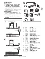
Place the tube drive adapter 

(7) 

on the motor and fix the

drive adapter with the parts 

(3 or 4)

Fix the square pin with the screws on the motor 

(5 or 6)

.

Fully unroll the shutter 

(a)

. Remove the shutter material

from the tube 

(b)

. Remove the manual control 

(c)

.

Remove the tube.

Push the motor 

(1)

completely into the tube. The limit

switch operates only if the drive unit is fully inserted.
Ensure that the adapter ring is pushed fully home. 

Do not

force it or strike it. Do not damage the tubular motor
by drilling!

Proceed according to the specific requirements for left-
sided 

(a)

or right-sided 

(b)

operation:

Secure the mounting bracket 

(8)

to the wall (use suitable

screws and plugs).

Insert the motor 

(a)

into the mounting bracket 

(8)

and

secure it.

Make sure the set screws for the limit adjustments
are accessible.
Don’t return the shutter material to the tube yet!

ELECTRICAL CONNECTION

Never connect more than one motor to a timer or
wall switch without using a central module – (h)
(available as an accessory), i.e. one central module

is required for each connected motor.

The illustration also shows the wall bracket on the drive side

(b)

, the motor 

(a)

; the steel tube 

(c)

; the end cap 

(d)

; and the

opposite wall bearing 

(e)

.

For a 

left-side

motor installation, follow the wiring diagram

exactly

as shown in the control accessory package.

For the correct direction of rotation in a 

right-side

motor

installation, electrical wires (brown & black) must be 

reversed

between the control accessory and the motor. (See instructions
packed with the accessory you have chosen).

Have the electrical hook-up done by a qualified electrician
in compliance with your local electrical code.

Accessories can be found in section L on page 4.

D

E

H

C

B

F

G

A

GB-3

SETTING THE LIMITS

Procedure for Adjusting 

“Open” and “Close” Positions

(refer to figure I for lefthanded installation)

#1 Limit Setting for “Shutter Open”

+    =   increase travel

–    =   decrease travel

#2 Limit Setting for “Shutter Close”

+    =   increase travel

–    =   decrease travel

Please observe that the limits of the motor only
operate in a complete installation.

Read the following instructions carefully 

before

making

any open or close limit adjustments.

To attach the shutter material on the tube, use ONLY the 3.9 x
6.5 mounting screws included (not suitable for RA10).
Otherwise, the drive might be damaged by screws which are
too long.

This instruction applies particularly to model RA10 (no
screws included). Use the appropriate fixing parts to
secure the shutter material to the tube. The drive may be
damaged by using screws which are too long.

IF ADJUSTMENTS ARE NEEDED, PROCEED AS FOLLOWS:

LIMIT ADJUSTMENT SCREW #1 - OPEN

Run the motor through an open cycle. 

©

If motor stops before shutter is fully opened:

Turn set screw #1 and open the shutter until desired
position is reached.

© 

If motor stops after shutter is fully opened:

Close shutter below desired position. Turn set screw #1 toward
– and open shutter again. Repeat this step as often as
necessary to reach the desired position

LIMIT ADJUSTMENT SCREW #2 - CLOSE

Run the motor through a close cycle. 

© 

If motor stops too soon (before shutter is fully closed): 

Turn set screw #2 and close shutter again, until 
desired position is reached.

©

If motor stops after shutter is fully closed:

Retract shutter above desired position. Turn set screw #2
toward – and close shutter again. Repeat this step as often as
necessary to reach the desired position.

I

Summary of Contents for MotorLift RA30

Page 1: ...RA10 RA20 RA30 RA50 Ouvre et ferme automatiquement les volets roulants Instructions Tubular Motor RA10 RA20 RA30 RA50 Automatically Opens and Closes Shutters Instructies Buismotor RA10 RA20 RA30 RA50...

Page 2: ...B a b c C 8 F G 8 1 D a c b d e E a b H A RA10 RA20 RA30 6 2 Series RA10 RA20 und RA30 Series RA50 4 7 3 RA50 1 7 5 a 8...

Page 3: ...u er Betrieb setzen Steuereinrichtungen in Sichtweite des angetriebenen Produktes in einer H he von ber 1 5m anbringen Ausreichend Abstand zwischen bewegten Teilen und benachbarten Gegenst nden sicher...

Page 4: ...ieht sich ausschlie lich auf die Reparatur oder den Ersatz von defekten Ger teteilen und deckt nicht die Kosten oder Risiken des Transports der defekten Teile oder Produkte Diese Garantie deckt keine...

Page 5: ...Zubeh r finden Sie in Sektion L auf Seite 4 D E H C B F G A EINSTELLUNG DER ENDPOSITIONEN Einstellverfahren f r Rolladen AUF und Rolladen ZU bei Linkseinbau siehe Abb I 1 Einstellung der Endposition f...

Page 6: ...ter Betrieb hat wom glich den berlastungsschutz des Antriebs ausgel st 15 Minuten warten und dann erneut starten Antrieb l uft mit Unterbrechungen Eine autorisierte Elektrofachkraft Zuleitungen pr fen...

Page 7: ...vant de proc der l installation Monter les dispositifs de commande port e de vue du produit correspondant une hauteur sup rieure 1 5 m du sol Garantir une distance suffisante entre les pi ces en mouve...

Page 8: ...a r installation d une unit r par e ou remplac e ou les piles de rechange Un produit sous garantie qui s av re tre d fectueux en mat riau et ou en main d uvre sera r par ou remplac au choix de Chamber...

Page 9: ...bles la section L en page 4 D E H C B F G A F 3 REGLAGE DE LIMITE Ouvert et Ferm Proc dure de r glage de limite N 1 R glage de limite pour le Volet ouvert augmentation de la course r duction de la cou...

Page 10: ...tricien autoris de v rifier le raccordement du c blage entre l interrupteur et le moteur et de le remplacer si n cessaire Le moteur ne s arr te pas S assurer que l adaptateur de l axe est plac fond co...

Page 11: ...RES 0908 EN60555 EN60335 1 per the provisions all amendments of EU Directives 73 23 EEC 89 336EEC Declaration of Incorporation Tubular Motor Model RA10 RA20 RA30 and RA540 when installed and maintaine...

Page 12: ...ith Chamberlain s instructions for installation operation and care failure to provide necessary maintenance and adjustment or any adaptations of or alterations to the products labor charges for disman...

Page 13: ...y you have chosen Have the electrical hook up done by a qualified electrician in compliance with your local electrical code Accessories can be found in section L on page 4 D E H C B F G A GB 3 SETTING...

Page 14: ...ittently Have the wiring connection between switch and motor checked by an authorized electrician Replace if necessary Motor does not shut off Check to be sure tube adapter is positioned all the way u...

Page 15: ...hoogte van tenminste 1 5 m Zorg voor voldoende afstand tussen bewegende delen en voorwerpen die zich in de nabijheid bevinden Nominaal koppel en inschakelduur moeten afgestemd zijn op de productspecif...

Page 16: ...nderhoud en de nodige bijstelling aanpassingen of wijzigingen van de produkten arbeidsloon voor het demonteren of opnieuw installeren van een gerepareerd of vervangen onderdeel of vervanging van de ba...

Page 17: ...ozen bedieningselement Laat de elektrische aansluiting doen door een erkend elektricien overeenkomstig de plaatselijk geldende elektriciteitsvoorschriften Toebehoren vindt u in sectie L op pagina 4 D...

Page 18: ...de overbelastingsbeveiliging van de motor zijn ingeschakeld Wacht een kwartier en probeer het nogmaals De motor draait met horten en stoten Laat de aansluiting van de draden tussen de schakelaar en d...

Reviews: