background image

12

The safety reversing sensor must be connected and
aligned correctly before the garage door opener will
move in the down direction.  

IMPORTANT INFORMATION ABOUT THE SAFETY
REVERSING SENSORS

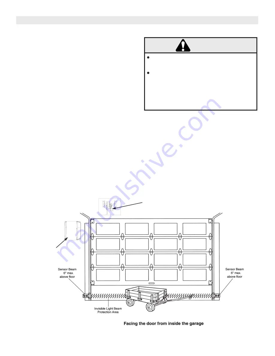
When properly connected and aligned, the sensor will
detect an obstacle in the path of its electronic beam.  The
sending eye (with an orange indicator light) transmits an
invisible light beam to the receiving eye (with a green indi-
cator light).
If an obstruction breaks the light beam while the door is
closing, the door will stop and reverse to full open position,
and the operator light will flash 10 times.

The photo eyes must be installed inside the garage so that
the sending and receiving eyes face each other across the
door, no higher than 6" above the floor.
Either can be installed on the left or the right of the door
as long as the sun never shines directly into the receiving
eye lens. 

The mounting brackets are designed to clip onto the track
of sectional garage doors without additional hardware.

THE PROTECTOR SYSTEM

If it is necessary to mount the units on the wall, the brack-
ets must be securely fastened to a solid surface such as
the wall frame.  Extension brackets are available if need-
ed.  If installing in masonry construction, add a piece of
wood at each location to avoid drilling extra holes in
masonry if repositioning is necessary.

The invisible light beam path must be unobstructed.  No
part of the garage door (or door tracks, springs, hinges,
rollers or other hardware) may interrupt the beam while
the door is closing.

FIGURE 8:

CABLE TENSION 
SENSOR ASSEMBLY

RJO OPERATOR

WARNING

CAUTION

WARNING

WARNING

Be sure power is not connected to the garage 
door opener BEFORE installing the safety 
reversing sensor.

To prevent SERIOUS INJURY or DEATH from a 

closing garage door.

- Correctly connect and align the safety reversing

sensor. This required safety device MUST NOT 
be disabled.

- Install the safety reversing sensor so beam is NO

HIGHER than 6” above garage floor.

Summary of Contents for RJO

Page 1: ...afety materials carefully n n Fasten the manual near the garage door after installation n n The door WILL NOT CLOSE unless the Protector Systemis connected and properly aligned n n Periodic checks of the opener are required to ensure safe operation n n The model number label is located on the front panel of your opener THE CHAMBERLAIN GROUP INC 845 LARCH AVE ELMHURST ILLINOIS 60126 1196 WWW CHAMBE...

Page 2: ...n Sensor 9 CONTENTS PAGE INSTALLATION CON T Install the Door Control 10 The Protector System 12 Install the Safety Reversing Sensor 13 POWER WIRING Power Wiring 11 Wiring Diagram 21 PRINTED CIRCUIT BOARD SETTING Receiver and Remote Control Programming 18 ADJUSTMENTS Model RJO Manual Disconnect 8 Limit Adjustments 16 Force Adjustments 16 Test the Safety Reverse System 17 Test the Protector System 1...

Page 3: ...instructions will call for hand tools as illustrated below WARNING CAUTION WARNING WARNING CAUTION To prevent damage to garage door and opener ALWAYS disable locks before installing and operating the opener ONLY operate garage door opener at 120V 60 Hz to avoid malfunction and damage Preparing your garage door Before you begin Disable locks Remove any ropes connected to garage door Complete the fo...

Page 4: ...th the unit may be used for this purpose Securely anchor the shipping base to the wall then mount the operator securely to the base This surface must a Be rigid to prevent play between operator and door shaft b Provide a level base c Permit the operator to be fastened securely with the drive shaft parallel to the door shaft The safety and life of the operator will be adversely affected if any of t...

Page 5: ...before installing opener 4 Disable all locks and remove all ropes connected to garage door before installing opener to avoid entanglement 5 Install garage door opener 6 feet or more above th floor 6 Mount emergency release handle 5 feet above floor 7 NEVER connect garage door opener to power source until instructed to do so 8 NEVER wear watches rings or loose clothing while installing or servicing...

Page 6: ...at suits your application NOTE Mounting Hardware Minimum 4 M8 Grade 5 Bolts Electrical Connections All fittings and conduit connections must meet local electrical code requirements OPTIMUM DISTANCE 12 15 7 TYP 6 Minimum Disconnect Handle 6 TYP 5 Minimum Preparation 1a The operator powerhead should be raised into its mounting position by use of a hoist or elevated platform 1b Acceptable lifting poi...

Page 7: ...nexpectedly NEVER use emergency release handle unless garage doorway is clear of persons and obstructions WARNING CAUTION W RELEASE CABLE KEYHOLE BRACKET ATTACHED TO OPERATOR EMERGENCY RELEASE HANDLE OVERHAND KNOT 3 Attach other side of door sprocket cover using 8 x 3 8 screws provided 4 Raise operator to approximate mounting position and position chain over operator sprocket 5 Raise or lower oper...

Page 8: ...ght will turn ON and remain lit for approximately 4 1 2 minutes when power is connected Then the light will turn OFF Replace thumb screws If the bulb burns out prematurely due to vibration replace with a standard neck Garage Door Opener bulb 75 WATT LIGHT BULB THUMB SCREW To prevent possible SERIOUS INJURY or DEATH from a falling garage door If possible use emergency release handle to disengage op...

Page 9: ...r installed to make up the difference EXAMPLE If you measure 2 7 8 you will need a 1 8 thick backer If you measure 3 you will need to install a 1 4 thick backer etc Repeat step 6 if a backer was installed 7 Drill pilot holes for the 5 CTS lag bolt mounting screws To prevent possible SERIOUS INJURY OR DEATH SECURELY mount the operator for proper operation of the Cable Tension Sensor Assembly WARNIN...

Page 10: ...l and the Maintenance Instruction label in a prominent location on the inside of the garage door If the label adhesive will not adhere to your garage wall surface or becomes loose with time use tacks to secure the label alongside the Door Control WARNING CAUTION To prevent possible SERIOUS INJURY or DEATH from electrocution Be sure power is not connected BEFORE installing door control Connect ONLY...

Page 11: ...move the 3 prong cord 3 Connect the black line wire to the screw on the brass terminal the white neutral wire to the screw on the silver terminal and the ground wire to the green ground screw The opener must be grounded Refer to figure 6 3a Re install internal shield 4 Re install the cover POWER WIRING LOOSEN 2 COVER SCREWS FOR ACCESS TO POWER CONTROL WIRING AND LIMIT FORCE ADJUSTMENTS FIGURE 5 FI...

Page 12: ...eye lens The mounting brackets are designed to clip onto the track of sectional garage doors without additional hardware THE PROTECTOR SYSTEM If it is necessary to mount the units on the wall the brack ets must be securely fastened to a solid surface such as the wall frame Extension brackets are available if need ed If installing in masonry construction add a piece of wood at each location to avoi...

Page 13: ...g the door Be sure there is enough clearance for the sensor beam to be unobstructed If additional depth is needed an extension bracket or wood blocks can be used Use bracket mounting holes as a template to locate and drill 2 3 16 diameter pilot holes on the wall at each side of the door no higher than 6 above the floor Attach the brackets to wall with lag screws not provided If using extension bra...

Page 14: ... black wires sufficiently to connect to the opener terminal screws white to IR white and white black to IR white black FIGURE 12 FIGURE 13 ALIGNING THE SAFETY SENSORS Plug in the opener The indicator lights in both the sending and receiving eyes will glow steadily if wiring connections and alignment are correct The sending eye orange indicator light will glow regard less of alignment or obstructio...

Page 15: ...alling rapidly and or unexpectedly 6 NEVER use emergency release handle unless garage doorway is clear of persons and obstructions 7 NEVER use handle to pull garage door open or closed If rope knot becomes untied you could fall 8 If one control force or travel limits is adjusted the other control may also need adjustment 9 After any adjustments are made the safety reversal system MUST be tested 10...

Page 16: ...ION WARNING WARNING CAUTION 16 If other problems persist call our toll free number for assistance 1 800 528 2806 FORCE ADJUSTMENTS The open down force adjustments are made by adjusting two control knobs inside the operator end panel One knob controls the drive force adjustment The second knob controls the sensitivity which is the change of force as seen by the operator To set the forces 1 Adjust t...

Page 17: ...close the door NOTE If you open close too many times the motor will stop due to thermal override cut off FORCE ADJUSTMENTS CON T TEST THE SAFETY REVERSE SYSTEM Without a properly installed safety reversal system persons particularly small children could be SERIOUSLY INJURED or KILLED by a closing garage door Safety reversal system MUST be tested every month If one control force or travel limits is...

Page 18: ... for changing the code setting or replacing the transmitter battery THERE ARE NO OTHER USER SERVICEABLE PARTS Tested to Comply with FCC Standards FOR HOME OR OFFICE USE Operation is subject to the following two conditions 1 this device may not cause harmful interference and 2 this device must accept any interference received including interference that may cause undesired operation Your garage doo...

Page 19: ...n l l P P FIGURE 14 FIGURE 15 TO ADD A REMOTE CONTROL 1 Press and hold the remote control push button See Figure 14 2 Then press and release the Smart learn button on the back panel of the opener in Figure 15 The indicator light on the panel will begin to blink and the opener light will flash once 3 Release the remote control push button Now the opener will operate when that remote control button ...

Page 20: ...crew terminal connections Check for incorrect wiring between sensors and opener Check for a broken wire Check alignment Check for an open wire to the receiving eye Check CTS switch closure Realign either sensor MANUAL RELEASE TEST CLOSE GARAGE DOOR then pull down on the red manual release handle and engage cable stop in slot of retaining bracket The operator output sprocket will dis connect If you...

Page 21: ... 8 7 6 5 4 3 2 1 RPM OPEN CLOSE YE YE GY WH BR PU WH BK BL RD YE PU GY WH GY GROUND GN BK WH CONTROL WIRING POWER WIRING GN BK WH N O N C COM CTS WIRING TRANSMITTING EYE RECEIVING EYE CTS SWITCH BK BK BK WH WH R1 CMN TB1 IR WHITE IR WH BK D1 SBC S1 SBC WIRING DIAGRAM ...

Page 22: ...17467 216A0149 171A0453 026B0073 028A0078 10 17729 75 13705 171A0384 175C0147 K72 16051 OUTPUT SHAFT KIT ITEM PART DESCRIPTION QTY O1 O2 O3 O4 O5 O6 Shaft Output 1 Sprocket 1 I D 32 Tooth Bushing 1 I D Keyed Shim Washer 1 I D 1 16 Thk E Ring 1 Roll Pin 5 16 X 2 Long 1 1 2 6 2 2 11 17943 15 48B32LXX 12 10715 80 206 11 87 E 100 86 RP10 200 K72 16050 REDUCTION SHAFT KIT ITEM PART DESCRIPTION QTY R1 R...

Page 23: ...23 ILLUSTRATED PARTS MODEL RJO ...

Page 24: ...ORMATION IS AVAILABLE 6 DAYS A WEEK CALL OUR TOLL FREE NUMBER 1 800 528 2806 HOURS 7 00 TO 3 30 p m Mountain Std Time MONDAY Through SATURDAY WHEN ORDERING REPAIR PARTS PLEASE SUPPLY THE FOLLOWING INFORMATION PART NUMBER DESCRIPTION MODEL NUMBER ADDRESS ORDER TO THE CHAMBERLAIN GROUP INC Electronic Parts Service Dept 2301 N Forbes Blvd Suite 104 Tucson AZ 85745 ...

Reviews: