background image

40

APPENDIX

STEP 8

SOLAR PANELS

NOT PROVIDED. SEE ACCESSORIES.

Solar Application requirements:

•   A minimum of one 10W solar panel (Model SOLPNL10W12V).

•   A maximum of three 10W solar panels in parallel (Model SOLPNL10W12V).

•  Battery Harness (Model K94-37236)

•   One 7AH battery or one 33AH battery

•   A heater cannot be used with a solar application.

Disconnect the expansion board if it is not in use to improve performance

We recommend LiftMaster low power draw accessories to minimize power 

draw, refer to accessory page. 

NOTE:

 Input solar power is 12 Vdc at 30 watts maximum.

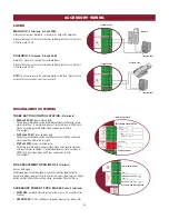
The solar panel(s) must be located in an open area clear of obstructions and shading for the entire day. The gate operator is not supported in northern 
climates where temperatures reach below -4˚F. This is due to cold weather and a reduced number of hours of sunlight during the winter months. Cycle 
rate may vary from solar chart for areas that reach below 32˚F. Solar panels should be cleaned on a regular basis for best performance to ensure 
proper operation. 

NOT AVAILABLE

1

1

2

3

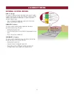
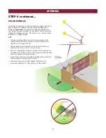
SOLAR ZONES

ZONE 1 (6 Hours of Sunlight/Day):

 Ideal for solar 

application

ZONE 2 (4 Hours of Sunlight/Day):

 Recommended 

for solar application

ZONE 3 (2 Hours of Sunlight/Day):

 Success of 

solar application will depend on type of gate 
operator and location of the solar panel

NOT AVAILABLE

3

2

1

Summary of Contents for RSW12U

Page 1: ...A TRAINED GATE SYSTEMS TECHNICIAN ONLY This model is for use on vehicular passage gates ONLY and not intended for use on pedestrian passage gates This model is intended for use in Class I and II vehic...

Page 2: ......

Page 3: ...INTENANCE CHART 29 BATTERIES 29 TROUBLESHOOTING 30 DIAGNOSTIC CODES 30 CONTROL BOARD LEDS 33 TROUBLESHOOTING CHART 34 APPENDIX 36 DUAL GATE SETTINGS 36 INSTALLATION TYPES 37 DETERMINE LOCATION FOR CON...

Page 4: ...accordance with the requirement however a single device is not required to cover both directions This operator is provided with Type A The installer is required to install additional entrapment prote...

Page 5: ...r activation must be located at least 6 feet 1 8 m away from any moving part of the gate and where the user is prevented from reaching over under around or through the gate to operate the controls Out...

Page 6: ...astm org 3 1 2 All openings shall be designed guarded or screened from the bottom of the gate to the top of the gate or a minimum of 72 in 1 83 m above grade whichever is less to prevent a 2 1 4 in 5...

Page 7: ...NTORY NOT SHOWN Documentation packet and hardware bag INTRODUCTION Operator Arm Assembly Cover Warning Signs 2 and Warranty Card Battery 12 Vdc 7AH Key 2 LiftMaster Monitored Retro Reflective Photoele...

Page 8: ...2 kg 12 ft 3 7 m 700 lbs 317 5 kg 10 ft 3 m 800 lbs 362 9 kg 8 ft 2 4 m 1000 lbs 543 5 kg 6 ft 1 8 m 90 Degree Travel Time 17 seconds Maximum Travel Range 115 degrees Maximum Daily Cycle Rate 250 cyc...

Page 9: ...freely and be supported entirely by its hinges Trench and install conduit Before trenching contact underground utility locating companies Conduit must be UL approved for low and high voltage Consider...

Page 10: ...th Ground Rod Check national and local codes for proper depth Warning Sign Photoelectric Sensors Edge Sensors INTRODUCTION OVERVIEW OF TYPICAL INSTALLATION SINGLE GATE DUAL GATE Identify your installa...

Page 11: ...measurements and location of the concrete pad 28 24 Outside Property Inside Property 29 5 35 5 11 2 46 25 10 Short Arm Long Arm Hinge Center Concrete Pad INSTALLATION To AVOID damaging gas power or o...

Page 12: ...32 inches a compact installation is necessary Refer to Appendix for compact installation instructions Caution If the gate is longer than 18 feet follow CHART A A 2 Suggestion The dimensions between th...

Page 13: ...ground and deeper than the frost line Ensure the pad is tall enough to avoid possible flooding 3 Secure the operator to the concrete pad with appropriate fasteners NOTE An alternative to a concrete p...

Page 14: ...ERATOR ARM LENGTH NOTE The length of the arm can be adjusted if necessary If adjusting the length ensure that both sections of the arm are adjusted proportionally Use the set screws on the arm to temp...

Page 15: ...Remove the set screws from the arm NOTE Completely weld around the outer tubing and bracket 5 Adjust the nuts on the operator arm so the operator arm fits snug on the output shaft yet still allows eno...

Page 16: ...If the operator does not receive the signal from the device it will not run An entrapment zone is every location or point of contact where a person can become entrapped between a moving gate and a sta...

Page 17: ...ctionality is based on the switch settings located next to the terminals Switch set to CLOSE gate reverses fully when obstruction is sensed Switch set to OPEN gate reverses 4 seconds when obstruction...

Page 18: ...connected to each operator Main power supply and control wiring MUST be run in separate conduits The battery is charged in the circuit by the integrated transformer The operator requires one 7AH batte...

Page 19: ...battery in place of the 7AH battery follow the instructions below The 33AH application requires the 33AH wire harness Model K94 37236 33AH BATTERY 1 Unplug the transformer 2 Unplug the J15 plug label...

Page 20: ...N button again on the primary operator The yellow NETWORK LED will light 4 Press and release the OPEN test button to assign this operator as network primary 5 Press and release the LEARN button on the...

Page 21: ...L power to the operator and plug the J15 plug into the control board DUAL GATE WIRE TYPE SHIELDED TWISTED PAIR CABLE 22AWG up to 200 feet 61 m 18AWG 200 1000 feet 61 305 m Wire must be rated at 30 Vol...

Page 22: ...18 lead in screw The basic installation is complete STEP 10 INSTALL THE COVER The operator cover consists of two pieces a rear cover and a front cover The front cover can easily be removed to access t...

Page 23: ...he MOVE GATE buttons to move the gate to the open or close limit 3 Press and release the SET CLOSE or SET OPEN button depending on which limit is being set 4 Press and hold one of the MOVE GATE button...

Page 24: ...Initial Limit and Force Adjustment section on page 21 ADJUSTMENT LIMIT AND FORCE ADJUSTMENT continued The operator is equipped with an automatic obstruction sensing feature If the gate encounters an o...

Page 25: ...its are designed to provide reasonable protection against harmful interference in a residential installation This equipment generates uses and can radiate radio frequency energy and if not installed a...

Page 26: ...teway 3 Create an online account by visiting www myliftmaster com 4 Register the LiftMaster Internet Gateway 5 Use an internet enabled computer or smartphone to add devices The LiftMaster Internet Gat...

Page 27: ...s for programming remote controls and the network 7 TIMER TO CLOSE dial The TIMER TO CLOSE TTC dial can be set to automatically close the gate after a specified time period The TTC is factory set to O...

Page 28: ...arm or gate is incorrectly installed B The gate does not meet specifications C Gate hinges are too tight or broken and the gate is not moving freely D The gate is moving and a car pushes the gate E A...

Page 29: ...l shadow loop detector when loop is positioned under the swing of the gate Holds open gate at open limit Only active when the gate is at the OPEN limit disregarded at all other times Pauses Timer to C...

Page 30: ...to Close momentary input logic as single button control and safeties remain active re enables Timer to Close ACCESSORY POWER 12 VDC MAX 500 mA 4 Terminals SWITCHED Switched ON with gate motion stays o...

Page 31: ...y IMPORTANT SAFETY INFORMATION To reduce the risk of SEVERE INJURY or DEATH READ AND FOLLOW ALL INSTRUCTIONS ANY maintenance to the operator or in the area near the operator MUST NOT be performed unti...

Page 32: ...DE NUMBER The second number shown after the code sequence number is the code itself 31 99 example 31 Refer to the chart on the following page for an explanation of each code CODE SEQUENCE NUMBER The f...

Page 33: ...oo much voltage on the battery Check harness Make sure there is NOT a 24V battery on a 12V system YES 41 Battery overcurrent Possible short of the battery charge harness Check harness Make sure you do...

Page 34: ...r canceling TTC 72 OPEN EYE EDGE triggered causing reversal or preventing opening 73 CLOSE EYE INTERRUPT triggered causing reversal preventing close or resetting TTC IF an obstruction occurred no acti...

Page 35: ...e BLINK Input active on other operator LOCK OFF Maglock relay inactive ON Maglock relay active STATUS LEDS INPUT POWER OFF OFF state ON AC charger or Solar power available BATT CHARGING OFF Not chargi...

Page 36: ...for a stuck on input b Check Stop button is not stuck on c Check Reset button d Charges batteries by AC or solar power or replace batteries e Check all Entrapment Protection Device inputs for a stuck...

Page 37: ...s with a command a Double entrapment occurred two obstructions within a single activation a Check for cause of entrapment obstruction detection and correct Press the reset button to shut off alarm and...

Page 38: ...accessory power draw c Old batteries d Solar panels are not getting enough sunlight a Add more solar panels b Reduce the accessory power draw by using LiftMaster low power accessories c Replace batter...

Page 39: ...compact installation If the operator arm will hit an obstruction when the gate is in the open position follow the directions for Compact Installation Inside Property Outside Property UPHILL DRIVEWAY...

Page 40: ...operator refer to accessories 4 Concrete Anchors 1 2 x 3 1 2 Below the frost line Check all national and local codes 6 Above Ground 28 Post Mount 24 24 32 STEP 1 DETERMINE LOCATION FOR CONCRETE PAD A...

Page 41: ...et Screws 23 25 1 2 STEP 4 POSITION THE GATE BRACKET COMPACT INSTALLATION ONLY NOTE It may be necessary to attach horizontal reinforcement to the gate before attaching the gate bracket Use the set scr...

Page 42: ...olar panel s must be located in an open area clear of obstructions and shading for the entire day The gate operator is not supported in northern climates where temperatures reach below 4 F This is due...

Page 43: ...tes Actual results may vary SOLAR GATE CYCLES PER DAY BATTERY CURRENT DRAW mA ZONE 1 ZONE 2 ZONE 3 7AH batteries Two 7AH batteries 33AH batteries 7AH batteries Two 7AH batteries 33AH batteries 7AH bat...

Page 44: ...panel s during the winter months when the sun sits lower in the sky The area around the solar panel s should be clear of shadows or obstructions to the sun for a 180 arc east to west Wire runs should...

Page 45: ...positive terminal of the battery Connect the black wire to the negative terminal of the battery 4 Connect the shorter red wire from the J15 plug new wire harness labeled DC Power to the red wire on t...

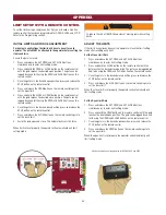
Page 46: ...n to set the close limit 8 Cycle the gate open and close This automatically sets the force When limits are set properly the operator will automatically exit limit setting mode ADJUST THE LIMITS If the...

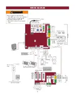
Page 47: ...ormer Yellow Blue Black Red Primary Secondary link to other gate operator Shielded Twisted Pair Cable Ground the shield of the cable to the chassis ground of each operator Photoelectric Sensors Field...

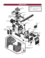
Page 48: ...PE Assembly K1A6408 Main Board with heat sink K1D8389 1CC Dust Guard K13 34729 Plug in Transformer APOW3 120V receptacle assembly K76 37016 Reset Switch K180A0357 Chassis K73 36109 1 Operator Cover wi...

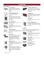
Page 49: ...UND ROUND MONITORED EDGE 4 FT Model WR4 WRAPAROUND ROUND MONITORED EDGE 5 FT Model WR5 WRAPAROUND ROUND MONITORED EDGE 6 FT Model WR6 Available November 2015 Available early 2016 REMOTE CONTROLS LiftM...

Page 50: ...kit allows the antenna to be remotely installed Model 86LM COMMERCIAL ACCESS CONTROL RECEIVER Access control receiver for up to 1 000 devices any combination of remote controls and wireless keyless e...

Page 51: ...D IN DURATION TO THE TWO YEAR LIMITED WARRANTY PERIOD SET FORTH ABOVE AND NO IMPLIED WARRANTIES WILL EXIST OR APPLY AFTER SUCH PERIOD Some states do not allow limitations on how long an implied warran...

Page 52: ...01 37841C COLOR 2015 LiftMaster All Rights Reserved 845 Larch Avenue Elmhurst Illinois 60126 1196 LiftMaster com...

Reviews: