background image

GATE 

CONFIGURATION

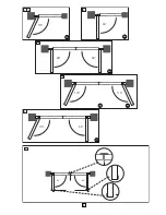
How far must the gate leaf open?

90 degrees or up to 115 degrees. An opening angle in excess of 115
degrees is possible to a limited extent but is not recommended.
Reason: the drive mechanism always runs at the same speed. The
further the gate has to be opened, the faster the gate leaf must
travel. Movement becomes more erratic and this subjects the fittings
and gate to extreme stresses (see 3A-F). 

Tip for professionals:

The time taken to reach the limit stop can be

controlled by deliberately selecting different A and B dimensions (left
+ right). However, this method of installing subjects the fittings to
high stresses and can cause the gate to run erratically. It is
recommended that only experienced gate installers adopt this
method.

GATE STOPS

A SWING GATE NEEDS A FIXED GATE STOP IN BOTH THE
OPEN AND CLOSE DIRECTIONS. 

Gate stops save wear and tear

on the drive mechanism, gate and fittings. Operating a gate without
fixed limit stops results in poor performance. It is often dangerous,
leads to premature wear and voids your warranty!

POST FIXING BRACKET

Choosing the correct location for the post fixing bracket has a
decisive impact on the subsequent functioning of the system. 

It

determines the distance between the motor's centre of motion and
the gate's centre of motion and hence the opening angle. These
dimensions are referred to as 

dimension A

and 

dimension B

. Do

not underestimate the effect that these dimensions have on correct
functioning and running. Try and achieve the best dimension for your
opening angle, as precisely as possible and suitable for all
circumstances. See Table 

(figure 4A-B) 

for dimensions A/B.

If the post is not wide enough, an extension piece must be fitted to it

(figure 5A)

. If the post is too thick, cut out part of it to make it thinner

(figure 5B)

.

To obtain ideal dimensions, it may be necessary to shorten or
lengthen the supplied hinge plate. In the case of gates that are to be
custom made, if the gate hinges are fitted on the posts appropriately,
it is possible to influence dimensions A and B. Before the final
mounting dimensions are determined, you should always check
whether or not there is any possibility that the corner of the drive
mechanism will hit the post as the gate swings.

INSTALLATION:

The drive mechanism exerts considerable force

against the post. Usually, acceptable mounting dimensions are
obtained if the supplied hinge plate is welded directly onto the post.
In the case of thick stone or concrete posts, the hinge must be
welded to a base plate and attached so that the plugs cannot work
loose during operation. Heavy-duty plugs where a threaded rod is
bonded into the masonry stress-free are more suitable for this
purpose than steel or plastic straddling plugs. In the case of
brickwork pillars, bolt on a relatively large steel plate that covers
several bricks and then weld the hinge plate to it. An angle plate
attached over the corner of the post is also a good means of fixing
the operators.

BEFORE YOU BEGIN

The drive mechanism needs room to the side permitting correct
installation of drive arms. Please make sure that this is available.
Gates affected by high wind loads must also be protected by an
(electric) lock.

There are many factors to consider when choosing the right drive
mechanism. Assuming that a gate functions properly, "startup" is the
most difficult phase, once the gate is in motion, significantly less force
is usually required to move it.

• Gate size: 

Gate size is a very important factor. Wind can brake or

distort the gate, thereby increasing the amount of force needed to
move it considerably.

• Gate weight: 

The weight of the gate in not as relevant as the size.

• Effect of temperature:

Low outdoor temperatures can make initial

startup more difficult (changes in the ground, etc.) or even prevent
it. 

• Operating frequency/Duty cycle:

24 volt drives can run permanently.

INSTALLATION CHECKLIST - PREPARATIONS

Check the carton contents and read the instructions carefully. Make
sure your gate equipment operates perfectly. The gate must run
evenly and smoothly and must not stick at any point. Remember that
the ground level may be several centimeters higher in winter. The
gate must be stable and as free of backlash as possible in order to
prevent any unwanted to and fro movement. The more smoothly the
gate leaf runs, the more sensitive the force adjustment must be.

Note down any materials you still need and obtain them before
starting to install. Heavy-duty plugs, bolts, gate stops, cables,
distribution boxes, tools, etc.

GATE TYPES

The gate type determines the location where the drive mechanism is
installed. If the gate stop is on the ground, the drive mechanism must
also be installed at a height that is as low as possible so that it
cannot twist the gate. Use only parts of the gate frame for fixing
purposes.

TYPE A, B, C

For steel gates, the gate fitting must be attached to the main frame.
If you are uncertain whether the available support is sufficiently
stable, reinforce it.

TYPE D, E, F 

In the case of wooden gates, the gate fitting must be through bolted.
It is advisable to fit a plate from the outside so that the fixing
brackets cannot become loose over time. Thin wooden gates must
also be reinforced in order to withstand the stresses encountered
(e.g. type F).

2

3

5

2-en

Summary of Contents for SCS500-24

Page 1: ...il SCS500 24 Instructions Gate Operator SCS500 24 Instrucciones Automatismo de Puerta SCS500 24 Istruzioni Automazioni per Cancelli SCS500 24 Instrukties Automatische hekaandrijving SCS500 24 Instru e...

Page 2: ...dem angetriebenen Teil und den umgebenden Teilen des Geb udes z B eine Wand aufgrund der ffnungsbewegung des angetriebenen Teils ber cksichtigt werden Automatisch gesteuerte Ger te m ssen vom Netz ge...

Page 3: ...Verbundanker bei denen ein Gewindestift spannungsfrei im Mauerwerk eingeklebt wird Bei gemauerten Pfeilern sollte eine gr ere Stahlplatte mehrere Steine berdeckend angeschraubt werden auf die dann die...

Page 4: ...h benutzt muss der Pfeilerbeschlag vor der ersten Inbetriebnahme gek rzt werden um am Antrieb gen gend Freiraum zu belassen Eine Missachtung f hrt zu einem Bruch des Beschlags am Antrieb Wird der Antr...

Page 5: ...environnantes du b timent par exemple une paroi doit tre consid r en raison du mouvement d ouverture de la pi ce entra n e D branchez le courant de l ouvre porte de garage avant de commencer toute r p...

Page 6: ...avec une tige filet e coll e sans pr contrainte dans la ma onnerie Dans le cas des piliers en ma onnerie il conviendrait de visser une grande plaque en acier d bordant sur plusieurs pierres et sur laq...

Page 7: ...e fixation du montant vous DEVEZ couper la partie restante de la plaque charni re avant la mise en service du bras La non r alisation de cette op ration provoquera l endommagement de la ferrure de fix...

Page 8: ...installation codes Power cables must only be connected to a properly earthed supply Any entrapment possibility by the moving wing between wing walls must be secured with safety edges or IR sensors Dis...

Page 9: ...ed so that the plugs cannot work loose during operation Heavy duty plugs where a threaded rod is bonded into the masonry stress free are more suitable for this purpose than steel or plastic straddling...

Page 10: ...ts and rings 7B If the centre or inner hole on the hinge plate is used to fix the post fixing bracket you MUST cut away the remaining section of the hinge plate before activating the arms Failure to d...

Page 11: ...uesta a tierra Cualquier posibilidad de quedarse aprisionado por la hoja en movimiento entre la hoja y la pared se deber proteger mediante cantos protectores o sensores infrarrojos Desconecte el siste...

Page 12: ...de pilares de alba iler a se montan en una placa de acero relativamente amplia que cubra diversos ladrillos y se suelda entonces la placa de bisagras encima Una escuadra de apoyo acoplada por encima...

Page 13: ...e de pilar se emplea el agujero de fijaci n medio o el interior dicho herraje debe ser recortado antes de la primer puesta en marcha para que en el automatismo disponga de suficiente espacio libre En...

Page 14: ...zato Al momento del montaggio necessario prendere in considerazione il rischio di intrappolamento tra la parte motorizzata e le parti circostanti dell edificio ad es una parete per il movimento di ape...

Page 15: ...viene incollata nella muratura e quindi con assenza di tensioni nel materiale sono pi adatti a tale scopo rispetto ai tasselli ad espansione in acciaio o plastica Sui pilastri in muratura necessario...

Page 16: ...stante della ferratura prima di procedere alla prima messa funzione al fine di lasciare sufficiente spazio libero sull attuatore La mancata osservanza di tale disposizione comporta la rottura della fe...

Page 17: ...e montage moet rekening worden gehouden met de actieradius van de draaiende vleugel in relatie tot omringende objecten bijvoorbeeld de muur van een gebouw en het daarmee verbonden risico van beknellin...

Page 18: ...spanningsvrij in het metselwerk wordt ingebracht beter geschikt dan stalen of kunststof keilbouten Bij gemetselde pijlers dient een tamelijk grote meerdere stenen bedekkende staalplaat te worden vast...

Page 19: ...van de scharnierplaat wordt gebruikt om de stijlbevestigingsbeugel te bevestigen MOET u het resterende gedeelte van de scharnierplaat verwijderen voordat u de arm inschakelt Als u dat niet doet wordt...

Page 20: ...ligada terra por um electrot cnico autorizado Aquando da montagem h que ter em conta o movimento de fecho entre a parte accionada e as partes adjacentes do edif cio p ex uma parede que se deve abertu...

Page 21: ...o ou material sint tico s o as ncoras compostas de colagem nas quais um pino roscado colado na parede sem tens o No caso de pilares revestidos de alvenaria dever ser aparafusada uma placa de a o maior...

Page 22: ...imeira coloca o em funcionamento para garantir espa o suficiente para o automatismo A inobserv ncia desta indica o leva ruptura da ferragem no automatismo N o utilize um martelo nem um objecto semelha...

Page 23: ...Key 2 14 8 cm 10 7 cm 102 5 cm Post Bracket Gate Bracket 2 A B C D E F 1 4...

Page 24: ...1150 900 900 900 1150 900 900 900 1150 1150 B 3 A C D E F 5...

Page 25: ...110 100 110 100 110 100 110 12 5 100 110 100 110 100 110 90 100 90 100 90 100 15 100 110 100 110 100 110 100 110 100 110 100 110 20 110 120 110 120 110 120 100 110 100 110 no 22 5 120 130 110 120 100...

Page 26: ...vy Steel Bracket Reinforce if necessary Back Steel Plates for Reinforcement Not provided Gate Hinge Gate Hinge Gate Hinge Back Steel Bracket Reinforce if necessary Heavy Steel Plate for Reinforcement...

Page 27: ...Post Bracket Gate Bracket 7 A B 8...

Page 28: ...hite 4 Yellow 5 Blue 6 Red CB24 24Vo l t RED RED BLUE BLUE 30VDC MOTOR MASTER MOTOR SECOND 24V 150mA BRN GRN WHT YEL MASTER BRN GRN WHT YEL SECOND LIG CONT BROWN GREEN WHITE BROWN GREEN WHITE YELLOW Y...

Page 29: ...mary Arm 12 KSWG 0623 Rear Connector with Pin 13 41ASWG 0119 Release Keys 14 Q230 Steel Bracket Mounting Plates 15 Q232 Bottom Washer and Nut NOT SHOWN K77 36389 Hardware Bag 14 15 11 12 13 14 9 0 m 2...

Page 30: ......

Page 31: ......
Page 32: ...chtlinie 2006 42 EG EG Elektromagnetische Vertr glichkeit 2004 108 EG EG Niederspannungsrichtlinie 2006 95 EG EG Bauprodukterichtlinie 89 106 EG Insbesondere wurden folgende harmonisierte Normen angew...

Reviews: