background image

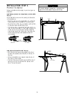
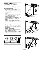
ASSEMBLY STEP 5

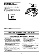
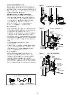
Attach the Belt Cap Retainer

• Position the belt cap retainer over the motor unit

sprocket so the two holes in cap align with the two
holes in mounting plate. Attach with 8x3/8" hex
screws provided.

You have now finished assembling your garage
door opener. Please read the following warnings
before proceeding to the installation section.

11

IMPORTANT INSTALLATION INSTRUCTIONS

1. READ AND FOLLOW ALL INSTALLATION WARNINGS

AND INSTRUCTIONS.

2. Install garage door opener only on properly balanced

and lubricated garage door. An improperly balanced
door may not reverse when required and could result in
severe injury or death. 

3. All repairs to cables, spring assemblies and other

hardware MUST be made by a trained door systems
technician before installing opener.

4. Disable all locks and remove all ropes connected to

garage door before installing opener to avoid
entanglement.

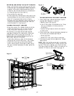
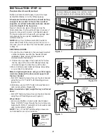
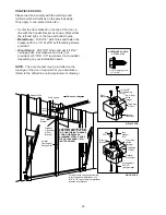
5. Install garage door opener 7 feet or more above floor.
6. Mount emergency release handle 6 feet above floor.
7. NEVER connect garage door opener to power source

until instructed to do so.

8. NEVER wear watches, rings or loose clothing while

installing or servicing opener. They could be caught in
garage door or opener mechanisms.

9. Install wall-mounted garage door control:

• within sight of the garage door 
• out of reach of children at minimum height of 5 feet
• away from all moving parts of the door.

10. Place entrapment warning label on wall next to garage

door control.

11. Place manual release/safety reverse test label in plain

view on inside of garage door.

12. Upon completion of installation, test safety reversal

system. Door MUST reverse on contact with a one-
inch high object (or a 2x4 laid flat) on the floor.

To reduce the risk of severe injury or death:

WARNING

CAUTION

WARNING

WARNING

ATTENTION

AVERTISSEMENT

AVERTISSEMENT

AVERTISSEMENT

Hex Screws
# 8 x 3/8"

Belt Cap
Retainer

Motor Unit 
Sprocket

Mounting Plate

Hex Screw
#8x3/8"

HARDWARE SHOWN 

ACTUAL SIZE

INSTALLATION

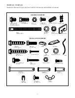
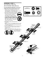
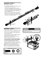
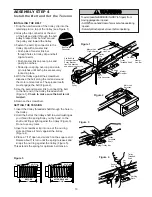
Summary of Contents for Security+ 9200-2K

Page 1: ...Fasten the manual near the garage door after installation The door WILL NOT CLOSE unless the Protector System is connected and properly aligned Periodic checks of the opener are required to ensure saf...

Page 2: ...roblem 34 Programming Pages 35 36 To add a hand held remote control 35 To erase all codes 35 Multi function remotes 35 To add or change a Keyless Entry PIN 36 Repair Parts Pages 37 38 Rail assembly pa...

Page 3: ...ich are under EXTREME tension Disable ALL locks and remove ALL ropes connected to garage door BEFORE installing and operating garage door opener to avoid entanglement Preparing your garage door Before...

Page 4: ...t bracket and additional fastening hardware may be required Installation Step 10 Depending upon garage construction extension brackets or wood blocks may be needed to install sensors Installation Step...

Page 5: ...G Support bracket fastening hardware is required See page 17 Safety Reversing Sensor Safety Reversing Sensor Header Wall Access Door Gap between floor and bottom of door must not exceed 1 4 ONE PIECE...

Page 6: ...ulley Bracket LOCK LIGHT 2 Safety Reversing Sensors 1 Sending Eye and 1 Receiving Eye with 2 Conductor White White Black Bell Wire attached Safety Sensor Bracket 2 Model 8200C 2K Only Your garage door...

Page 7: ...ded Shaft 1 Wing Nut 14 20 2 Hex Screw 5 16 18x7 8 4 Carriage Bolt 1 4 20x1 2 2 Spring Trolley Nut 1 Nut 5 16 18 4 Clevis Pin 5 16 x2 3 4 1 NOTICE Handle Insulated Staples 30 Clevis Pin 5 16 x1 1 Dry...

Page 8: ...versals 3 Assemble lock nuts ensure alignment and tighten NOTE If T rail is not assembled exactly as shown trolley will not travel smoothly along length of rail or it will hit against nuts 4 Position...

Page 9: ...t pulley bracket Remove the two 5 16 18x1 2 washered screws mounted in the top of the motor unit Align the holes in the back section of the T rail with the holes in the motor unit Fasten the rail with...

Page 10: ...wdriver SETTING THE TENSION 1 Insert the trolley threaded shaft through the hole in the trolley 2 Hold the belt at the trolley shaft to avoid twisting as you thread the spring trolley nut by hand on t...

Page 11: ...ener to avoid entanglement 5 Install garage door opener 7 feet or more above floor 6 Mount emergency release handle 6 feet above floor 7 NEVER connect garage door opener to power source until instruct...

Page 12: ...g horizontal line on the header wall 2 above the high point This height will provide travel clearance for the top edge of the door Proceed to Step 2 page 14 One piece door with horizontal track To pre...

Page 13: ...shown Measure the distance from the top of the door to the floor Subtract the actual height of the door Add 8 to the remainder See Example 3 Close the door and draw an intersecting horizontal line on...

Page 14: ...arage Door Travel Vertical Center Line Header Wall Garage Door UP CEILING MOUNT ONLY Wall Mounting Holes Optional Wall Mounting Holes The nail hole is for positioning only You must use lag screws to m...

Page 15: ...ry support to allow the rail to clear the spring Position the rail bracket against the header bracket Align the bracket holes and join with a clevis pin as shown Insert a ring fastener to secure Heade...

Page 16: ...ing an ideal door to T rail distance Raise the opener onto a stepladder You will need help at this point if the ladder is not tall enough Open the door all the way and place a 2x4 laid flat on the top...

Page 17: ...ntered over the door or in line with the header bracket if the bracket is not centered above the door 7 Remove the 2x4 Operate the door manually If the door hits the rail raise the header bracket 8 Gr...

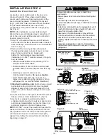
Page 18: ...te to 2 and white red to 1 Fig 5 5 Use tacks or staples to permanently attach entrapment warning label to wall near door control and manual release safety reverse test label in a prominent location on...

Page 19: ...rope to prevent slipping Thread the other end of the rope through the hole in the release arm of the outer trolley Adjust rope length so the handle is 6 feet above the floor Secure with an overhand k...

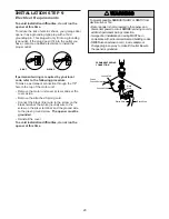
Page 20: ...screw on the brass terminal the white neutral wire to the screw on the silver terminal and the ground wire to the green ground screw The opener must be grounded Reinstall the cover To avoid installati...

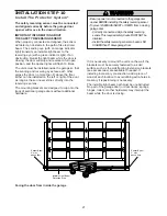
Page 21: ...nstalled on the left or right of the door as long as the sun never shines directly into the receiving eye lens The mounting brackets are designed to clip onto the track of sectional garage doors witho...

Page 22: ...e track as shown in Figure 1 If your door track will not support the bracket securely wall installation is recommended Wall installation Place the bracket against the wall with curved arms facing the...

Page 23: ...the sending eye wing nut and readjust aiming directly at the receiving eye Lock in place Loosen the receiving eye wing nut and adjust sensor until it receives the sender s beam When the green indicato...

Page 24: ...ding on your door s construction Metal or light weight doors using a vertical angle iron brace between the door panel support and the door bracket Drill 3 16 fastening holes Secure the door bracket us...

Page 25: ...he door if required for your installation Refer to the dotted line optional placement drawing Header Wall Vertical Centerline of Garage Door Finished Ceiling Optional Placement of Door Bracket Header...

Page 26: ...r apart as possible to increase door arm rigidity Figure 3 Hole alignment alternative If holes in curved arm are above holes in straight arm disconnect straight arm Cut about 6 from the solid end Reco...

Page 27: ...als 2 of trolley travel Closed door adjustment decrease DOWN travel limit Turn the DOWN limit adjustment screw clockwise 5 complete turns 27 Nuts 5 16 18 Lock Washers 5 16 Ring Fastener Straight Arm S...

Page 28: ...travel Turn the down limit adjustment screw counterclockwise One turn equals 2 of travel If door still won t close completely and the trolley bumps into the pulley bracket see page 4 or 5 try lengthe...

Page 29: ...ake small adjustments until the door completes a close cycle After each adjustment run the opener through a complete travel cycle Do not increase the force beyond the minimum amount required to close...

Page 30: ...h board remove the obstruction and run the opener through 3 or 4 complete travel cycles to test adjustment IMPORTANT SAFETY CHECK Repeat Adjustment Steps 1 2 and 3 after Each adjustment of door arm le...

Page 31: ...purchase a new remote or if you wish to deactivate any remote follow the instructions in the Programming section Activate your opener with any of the following The hand held Remote Control Hold the la...

Page 32: ...minute interval can be changed to 1 1 2 2 1 2 or 3 1 2 minutes as follows Press and hold the Lock button until the light blinks about 10 seconds A single blink indicates that the timer is reset to 1...

Page 33: ...er doesn t operate from either the Door Control or the remote control Does the opener have electric power Plug a lamp into the outlet If it doesn t light check the fuse box or the circuit breaker Some...

Page 34: ...eview Adjustment Step 2 on page 29 If door reverses in the fully closed position decrease the travel limits Adjustment Step 1 Repeat safety reverse test after adjustments to force or travel limits The...

Page 35: ...bar on the Multi Function Door Control all three buttons are held 4 Release buttons when the motor unit lights blink It has learned the code If light bulbs are not installed two clicks will be heard...

Page 36: ...r buttons for the present PIN then press and hold the button The opener light will blink twice Release the button 2 Press the new 4 digit PIN you have chosen then press Enter The motor unit lights wil...

Page 37: ...embly hardware kit see page 7 KEY PART NO NO DESCRIPTION 1 41A5273 8 Multi function door control panel 2 41A5056 Multi function remote control 3CGI housing only no circuit board 3 10A20 3V2032 Lithium...

Page 38: ...harness assembly with plug 6 41A5021 5F Receiver logic board assembly Complete with Logic board 7 41A3673 1 End panel w all labels 8 175B88M Light socket 9 108D34 Lens 10 30B363 Capacitor 1 2 h p KEY...

Page 39: ...door automatically from outside when remote control is not handy 8 Foot Rail Extension Kit To allow an 8 foot door to open fully Extension Brackets Optional For safety sensor installation onto the wa...

Page 40: ...at a unit replacement is needed we may do so with either a new or reconditioned unit of the same or equal design Obtaining Service It s as easy as calling our toll free hotline at 1 888 528 6305 We wi...

Reviews: