♦
ASSEMBLY OF DRIVE BASE PLATE
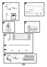
The drive base plate can be embedded in concrete, mounted
with dowels or welded on to the underlying surface.
♦
ASSEMBLY OF MOTOR AND GEAR UNIT
The drive is now placed on the threaded bolts of the base
plate as shown in Illustration 3. The height should be
adjusted so that the distance between the cogwheel and the
toothed rack is about 1 - 2 cm. The long holes can be used to
position the drive in relation to the toothed rack so as to
comply with the assembly dimensions of Illustration 4.
♦
ASSEMBLY OF TOOTHED RACK
After the motor and gear unit has been mounted, the rack rail
can be mounted on the gate. Suitable mounting screws
should be used to mount the rack to the gate. The simplest
and fastest method of mounting the rack rail is to use self-
tapping and self-cutting steel screws (e.g. 6.3 x 25 PIAS
screws from Würth or the like).
If such screws are not available and if steel gates are used,
an M6 thread must be cut. Please take care to ensure that the
mounting screws are placed in the middle of the long holes on
the mounting holder, so that the position of the rack rail can
be corrected later.
NB: The simplest way of mounting the rack rail is to place
it on the drive cogwheel of the motor, unlock the motor,
and push the gate gradually open with the rack rail on it,
screwing in the screws one by one in the process. This
will ensure optimum meshing of the rack rail with the
cogwheel.
♦
UNCOUPLING OF DRIVE
A lockable uncoupling device is provided so that the gate can
be opened by hand in case of a power failure. The uncoupling
process is shown in Illustration 6. The uncoupling lever ca be
unlocked and opened with the key, which releases the
connection between the cogwheel and the worm gear. If the
lever is returned to its original position, the drive is
automatically coupled again.
♦
ASSEMBLY OF LIMIT-SWITCH BRACKETS
The drive should be uncoupled before this part of the
assembly work is carried out. Slide the gate into the closed
position. Mount the limit switch bracket such that the roller of
the switch is situated approximately int the middle of the
bracket. Repeat this process for the open position. The
bracket should be mounted with M6 screws with shims and
washers. It is recommended that a 4.8mm Ø hole be drilled in
the toothed rack and an M6 thread cut in it. After final
adjustments, the bracket can be fixed in place with the screw.
♦
ELECTRICAL CONNECTIONS
Details of the electrical connections may be found in the
instructions for the
logic control box.
OPERATION
The sliding gate actuator can be operated by the remote
control. After disengaging the drive coupling using the key
provided, the gate can be operated manually.
Various operation modes can be preset by changing the dip
switches on the electronic control.
3
♦
MONTAGE DER ANTRIEBSGRUNDPLATTE
Die Antriebsgrundplatte kann einbetoniert, angedübelt oder
auch angeschweißt werden.
♦
MONTAGE DER MOTOR- UND GETRIEBEEINHEIT
Der Antrieb wird dann gemäß Abb. 3 auf die Gewindebolzen
der Grundplatte gesetzt. Die Höhe ist so einzustellen, daß
zwischen Zahnrad und Zahnstange ca. 1 - 2 cm Abstand ist.
Mittels der Langlöcher kann der Antrieb so eingestellt
werden, daß seine Lage zur Zahnstange den Montagemaßen
aus Abb. 4 entspricht.
♦
MONTAGE DER ZAHNSTANGE
Nachdem die Motor- und Getriebeeinheit montiert ist, kann die
Zahnschiene am Tor befestigt werden. Dazu sind an der
Zahnschiene angespritzte Halterungen mit Langlöchern für die
Befestigungsschrauben vorhanden. Am schnellsten und
einfachsten erfolgt die Montage der Zahnschiene mit
selbstbohrenden und selbstschneidenden Stahlschrauben (z.B.
PIAS-Schrauben 6,3 x 25 von der Fa. Würth oder ähnliches).
Stehen solche Schrauben nicht zur Verfügung, muß bei
Stahltoren ein M6-Gewinde geschnitten werden. Bitte beachten
Sie, daß die Befestigungschrauben in der Mitte der Langlöcher
am Befestigungshalter angebracht werden, damit die Position
der Zahnschiene später noch korrigiert werden kann.
Hinweis: Am einfachsten läßt sich die Zahnschiene
montieren, wenn man die Zahnschiene bei der Montage
auf dem Antriebszahnrad des Motors auflegt, den Motor
entriegelt und durch Weiterschieben des Tores mit der
aufgelegten Zahnschiene diese Stück für Stück
festschraubt. Dadurch ist immer garantiert, daß die
Zahnschiene mit dem Zahnrad optimal im Eingriff ist.
♦
ENTKUPPLUNG DES ANTRIEBES
Um das Tor bei Stromausfall von Hand betätigen zu können, ist
eine versperrbare Entkupplungsvorrichtung eingebaut. Die
Entkupplung ist in Abb. 6 dargestellt. Der Entkupplungshebel
kann mit Hilfe das Schlüssels herausgeklappt werden. Dadurch
löst eine Klauenkupplung die Verbindung zwischen Zahnrad und
dem selbsthemmenden Schneckengetriebe. Wird der Hebel
zurückgeklappt, erfolgt die Wiedereinkupplung automatisch.
♦
MONTAGE DER ENDSCHALTER
Vor der Montage ist der Antrieb zu entkuppeln. Montieren Sie
dann wie in Abb. 5 gezeigt die beiden Endschalterbügel so,
daß die Rolle des Endschalters etwa in der Mitte des Bügels
steht. Zu diesem Zweck schieben Sie das Tor in die jeweilige
gewünschte Endposition. Die Bügel sind durch M6-
Schrauben mit Beilagscheiben und Federring zu befestigen.
Bohren Sie dazu in die Zahnstange ein Loch mit 4,8 mm
∆
und schneiden Sie ein Gewinde M6. Die Bügel können dann
nach der endgültigen Einstellung durch die M6-Schrauben
gesichert werden.
♦
ELEKTRISCHER ANSCHLUß
Näheres zum elektrischen Anschluß kann der Anleitung zur
Steuerelektronik werden.
BEDIENUNG
Der Schiebetoröffner kann durch Taster, Schlüsselschalter
oder schlüssellose Schalter oder per Fernbedienungsset
eingeschaltet werden: Nach Entkuppelung des Antriebs mit
dem zugehörigen Schlüssel kann das Tor von Hand geöffnet
werden. Der Funktionsablauf nach Betätigung des
Befehlgebers (Fernbedienung, Taster etc) hängt von der
Einstellung der vier Dippschalter der Steuerelektronik ab.
D
GB


