5
General information and conditions for set-up.
Before installing the gate operator ensure that the gate is running smoothly. The weight of the door is not allowed to be completely placed on the motor shaft.Ensure that
all the required cables (power cable, accessory cables etc) are prepared and laid correctly before the base plate is installed in the concrete.
NOTE:
All crushing points must be secured by an entrapment protection according the to EU: EN 12453, EN 60335-2-103; GB (UK, NI): BS EN 12453, BS EN 60335-2-103.
SL400EVK, SL600EVK, SL1000EVK
Herewith you start mechanical installation of the gate operator.
Mounting Plate
90 - 100 mm
Rack
GA
TE
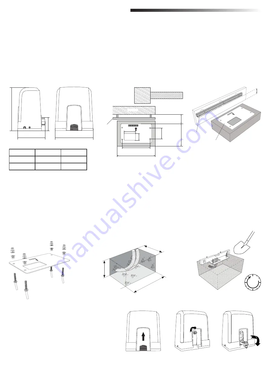
Picture 2
5.1 Dimensions of Gate and Operator
SL400EVK
5 m
400 kg
SL600EVK
8 m
600 kg
SL1000EVK
12 m
1000 kg
304
218
270
88
Picture 5
Picture 4
Picture 3
1. Take the anchor screw and put one nut untill the bottom of the tread. Add a washer and insert it from the bottom into base plate. Secure from top with a second nut.
2. Repeat for remaining 3 anchor screws (see picture 3).
3. Get the prepared cables (see picture 4) through the hole in the base plate.
4.
Set the base plate into prepared concrete work. Ensure the plate is poisitoned correctly to the gate respecting the required space to gate and rack (see picture 1). The
arrow on the base plate needs to show towards gate. Align the base palte and finalise the concrete work.
5. Let the concrete base dry for at least 24h before proceeding (see picture 5).
NOTE:
When installing a base plate ensure that later operator mounting and position adjustment with the setting screws is still possible at later stages if required.
5.2 Installing Base Plate
GATE
24h
5. MECHANICAL INSTALLATION
• Remove the small front plastic cover from the operator.
• Put the key into keyhole and turn it right 90°.
• Pull the lever down.
To re-engage the operator follow the procedure backwards.
5.3 Emergency Release Mechanism
Picture 6
Rack
Gate
60
270
170
104
60
244
100
GATE
Picture 1


