GB-5
OPERATION
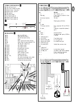
LED MONITORS
The system has six LED monitors which can be used for error
analysis or function control purposes.
LED 1
Yellow
ON = emergency stop vacant or
wire jumper available.
LED 2
Green
ON = signal from switch or radio
is present (open gate
fully).
LED 3
Green
ON = signal from switch or radio
is present (open gate
partially).
LED 4
Red
ON = Infrared Senor(s) vacant
or wire jumper available.
LED 5
Red
ON = OPEN limit switch
activated
LED 6
Red
ON = CLOSE limit switch
activated
LED 7
Red
Flashes slowly =
OK
Flashes quickly =
connection error and/or short
circuit in 120 volt area.
Both limit switches have been
ACTIVATED simultaneously!
9 – 10
It is possible to connect a gate
status LED that indicates the
given state of the gate.
OFF
= gate closed
Flashes slowly
= gate opening
ON
= gate open
Flashes quickly
= gate closing
FUSES
F1
3,15A, 250V
Main fuse
Protects the control
unit/transformer/flashing lamp/motor in
case of a short circuit
F2
0,5A, 250V
24AC supply
Reacts in case of short circuit or
overload on terminals 20 – 21
F3
0,315A, 250V
Fuse for logic circuitry
Push-button, emergency stop, light
barrier, receiver
Never use stronger fuses than those prescribed!
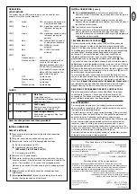
INITIAL OPERATION
DEFAULT SETTINGS
(1)
Connect drive in accordance with the attached connection
instructions
(2)
Put gate in semi-open position and engage motor
(3)
Adjust motor control unit to following default settings:
A
- Set force adjustment to 30%.
B
- Deactivate automatic close mode
(DIP switch 1 to OFF and 2 to ON)
.
C
- Set running time to 30%.
(4)
Switch on 120V power supply
(5)
Start motor control unit by pressing test push-button; the gate
should now open. If the gate closes, the connection leads to the
motor + limit switches (4 + 6) need to be swapped around.
Make sure you switch off mains supply prior to swapping leads
around!
(6)
Repeat steps 2 and 5 until desired functionality has been
established.
(7)
Adjust
potentiometer C
(brake) to set braking force for gate.
Small or light gates need no active brake.
INITIAL OPERATION (
CONTD
.)
(8)
Adjust
potentiometer A
to set the force generated by the
motors such that it is sufficient to just open and close the gate in
a proper manner.
(9)
Run through several complete cycles to test how the gate
behaves when operated and note whether it switches off when it
reaches the limit switches.
(10)
Test Infrared sensor functionality
(11)
Should you prefer a different programme (automatic closing
mode), wait until the end before changing the setting. Refer
back to the instructions to ascertain what impact the programme
selected has on functionality.
TEACHING IN REMOTE CONTROL
The radio remote control is licensed by the Post Office and costs
nothing to operate. It works on the basis of a private security code
(approx. 3.5 billion code options) that is pre-programmed via computer.
Your sliding gate drive can thus only be activated by a correspondingly
coded handset. The range obtained depends on the given local
environment. The receiver element of the motor control has an
integrated self-learn function. It can be set to the handset's pre-
programmed code by pressing the self-learn push-button
(fig. 13)
.
The control unit has two self-learn channels and is therefore able to
partially open a gate (pedestrian function) or open or close it fully via
appropriate operation of the handset. Should, for instance, channel 1
(1)
receive the handset's remote control code, the gate will only open
partially. If you teach the remote control on to channel 2
(2)
, you will
be able to open the gate completely.
To memorise the code, all you need do is press the button of your
choice on the handset and keep it depressed while, at the same time,
briefly pressing the self-learn button on the electronic unit with the
other hand.
Repeat this procedure for all handsets. Please note:
If
you release the given push-button before the self-learn LED has
stopped flashing, the remote control code will not be accepted.
DELETION OF PROGRAMMED REMOTE CONTROL CODE
Press the appropriate self-learn button
(1 or 2)
on the receiver
control board for approx. 10 seconds until the self-learn LED
extinguishes. The codes previously 'learned' and allocated to the
given self-learn button have thus been deleted.
REPROGRAMMING
For reprogramming purposes, the coding procedure mentioned
above should be repeated for all the remote controls in use and/or
their appropriate operating buttons.
The radio remote control's range varies according to the given local
environment. Keep the push-button on the handset depressed until
such time (approx. 2 seconds) as the gate is seen to move.
In the frequency ranges licensed by the German Post Office for gate
drives, there are also radio-operated systems in use for medical,
industrial, scientific, military and private purposes with, in some
cases, very powerful transmitting capabilities. Should you be in the
vicinity of such systems, this may cause your radio remote control to
suffer from reduced range or temporary interference.
Your radio remote control is digitally coded, i.e. accidental operation
of the gate drive is more or less impossible.
13
D e c l a r a t i o n o f C o n f o r m i t y
Automatic Gate Opener..........................................................SLY500E/K-120
as well as the Control unit ................................................................CB2-120
is in conformity to the applicable
sections of Standards.................................................EN55014, EN61000-3,
..........................................................EN60555, EN60335-1, & ETS 300 683
per the provisions & all amendments
of the EU Directives .................................................73/23/EEC, 89/336EEC
D e c l a r a t i o n o f I n c o r p o r a t i o n
Automatic Gate Opener Models SLY500E/K-120 and the control unit
CB2-120, when installed and maintained according to all the Manufacturer’s
instructions in combination with a Gate, which has also been installed and
maintained according to all the Manufacturer’s instructions, meets the
provisions of EU Directive 89/392/EEC and all amendments.
I, the undersigned, hereby declare that the equipment
specified above and any accessory listed in the manual
conforms to the above Directives and Standards.
Chamberlain GmbH
D-66793 Saarwellingen
May, 2002
Colin B. Willmott
Chief Engineer


