background image

Antenna Spoke Base Series 

Page 2 


Table of Contents


Introduction .............................................................................................................................................. 3 

CHA Antenna Spoke Base Series Antenna Description ............................................................................. 3 

Parts of the CHA Antenna Spoke Base Series ........................................................................................... 3 

Assembling the CHA SPIDER ASB

TM

 ........................................................................................................... 5 

Assembling the CHA QUAD ONE ............................................................................................................... 6 

Tuning Tips When Using the Antenna Spoke Base Series ......................................................................... 9 

Selection of Antennas for the Antenna Spoke Base Series ....................................................................... 9 

Troubleshooting ...................................................................................................................................... 10 

Specifications .......................................................................................................................................... 10 

Warranty ................................................................................................................................................. 11 

Accessories .............................................................................................................................................. 11 

Chameleon Antenna

TM

  Products ............................................................................................................ 11 

References .............................................................................................................................................. 12 


 WARNING! Never mount this, or any other antenna near power lines or utility wires! Any materials: 

ladders, ropes, or feedlines that contact power lines can conduct voltages that kill. Never trust insulation to protect 
you. Stay away from all power lines. 
 

 WARNING! Never operate this antenna where people could be subjected to high levels of RF exposure, 

especially  above  10  watts  or  above  14  MHz.  Never  use  this  antenna  near  RF  sensitive  medical  devices,  such  as 
pacemakers. 
 
All information on this product and the product itself is the property of and is proprietary to Chameleon Antenna

TM

Specifications are subject to change without prior notice. 


!


!


Summary of Contents for Antenna Spoke Base Series

Page 1: ...Portable Dipole Antenna Spoke Base Series User Guide Nevada USA WWW CHAMELEONANTENNA COM VERSATILE DEPENDABLE STEALTH BUILT TO LAST...

Page 2: ...nces 12 WARNING Never mount this or any other antenna near power lines or utility wires Any materials ladders ropes or feedlines that contact power lines can conduct voltages that kill Never trust ins...

Page 3: ...e CHA UMB U Bolt Base is made from a massive aluminum extrusion and has all stainless steel hardware Antennas and antenna accessories built by Chameleon AntennaTM are versatile dependable stealthy and...

Page 4: ...U Bolt Base CHA UMB U Bolt Base enables the Antenna Spoke Base to be attached to an antenna mast e Large U Bolt The Large U Bolts quantity 2 are used to hold the U Bolt Base d on an antenna mast up t...

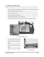
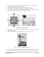
Page 5: ...Small U Bolt Holes j of the U Bolt Bracket 4 If your antenna mast is greater than 1 3 8 and less than or equal to 1 3 4 insert the two Large U Bolts e through the Large U Bolt Holes i of the U Bolt B...

Page 6: ...Antenna Whip Attachment viewed from below 12 Raise the antenna mast 13 Install non conducting guy lines not supplied but available as an accessory if necessary The assembled and erected portable dipo...

Page 7: ...he top of the mast and the base of the U Bolt Base as shown in plate 4 to avoid the heads of Hex Bolts g Plate 5 CHA QUAD ONE Antenna Spoke Base 8 Evenly tighten the Nuts on the U Bolts so that the ma...

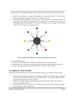
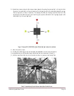
Page 8: ...rked with Red pair 1 and the 20m pair would be attached to the Couplings marked with Yellow pair 2 as shown in figure 2 Figure 2 Example CHA QUAD ONE Antenna Whip Attachment viewed from below 11 Raise...

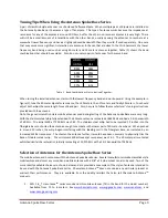
Page 9: ...were very long With the stainless steel whip fully extended the 40 meter antenna resonated at 6650 KHz and had a 2 0 1 bandwidth of 60 KHz The initial SWR at 7200 KHz was 16 1 The stainless steel whi...

Page 10: ...plings you are testing Four of the Couplings one from each pair as shown in plate 2 should have zero resistance The other four Couplings the ones on the opposite side should have infinite resistance M...

Page 11: ...onantenna com for current prices and availability or see our website www chameleonantenna com Guying System The Universal Guying System CHA UGS is recommended to stabilize the erected Antenna Spoke Ba...

Page 12: ...djustment with most modern external antenna tuners No masts or guying are required CHA TD Tactical Dipole The CHA TD Tactical Dipole Antenna has been designed as an add on for the CHA HYBRID MINI MICR...

Reviews: