CHA 40/20 FD
Page 5
which is the standard for interoperable HF communications, is an automated method of finding a frequency in the
OWF and establishing and maintaining a communications link.
Even under optimal conditions, there is a gap between where ground waves end (around 40 to 90 miles) and the sky
wave returns to Earth on the first hop (around 300 miles). NVIS propagation can be used to fill this gap. The
frequency selected must be below the critical frequency, so NVIS is can normally only be used on frequencies from
around 2 to 10 MHz. Frequencies of 2
–
4 MHz are typical at night and 4
–
8 MHz during the day.
Parts of the Antenna
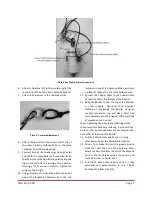
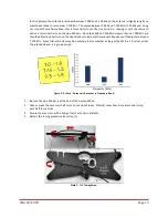
The Fan Dipole antenna is comprised of the following components, see plate (2):
Plate 2. Fan dipole Components.
a.
BALUN.
The BALUN (BALanced to UNbalanced) center transformer is used to match the antenna and
coaxial cable, preventing feedline radiation. The BALUN is also used as the mechanical and electrical
center attachment points for the antenna.
b.
Top Eyebolt.
The Top Eyebolt is located on top of the BALUN and is used as the mechanical attachment
points for the Antenna Wires and to suspend the center of the antenna.
c.
Antenna Connection.
The Antenna Connections are located on the sides of the BALUN and are used for
electrical connection of the Antenna Wires.
d.
Coaxial Cable Connection.
The Coaxial Cable Connection is located on the bottom of the BALUN. It is a
UHF Socket (SO-239) and is used to connect the coaxial cable to the antenna.
e.
Antenna Wire.
The Fan Dipole antenna consists of four Antenna Wires. Each are one leg of a dipole. The
two 7 MHz legs are 33 feet in length and the 14 MHz legs are 17 feet in length.
f.
Spade Lug
. The Spade Lugs are located at the center end of the Antenna Wires and are used to
electrically connect the Antenna Wires to the BALUN.


