CHA 40/20 FD
Page 6
g.
Insulator
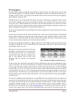
. The Insulators are located at each end of the Antenna Wire. They are used to electrically
isolate and mechanical attach the Antenna Wires.
h.
Carabiner.
The two Carabiners are used to mechanically attach the center end of the Antenna Wires to
the BALUN, providing strain relief.
i.
Line Winder.
The Line Winder is used to store the Antenna Wires and enables rapid deployment and
recovery of the Fan Dipole antenna.
j.
Paracord.
(not supplied)
Four 25-foot lengths
of nylon kernmantle line, “Paracord”, are recommended to
attach the ends of the Antenna Wires to Tent Stakes or other supports (such as trees or fence posts)
enabling installation versatility.
k.
Coaxial Cable.
(not supplied)
The Coaxial Cable is used to connect the Fan Dipole to the Radio Set. The
Coaxial Cable must have a 50 Ohm impedance and UHF Plugs (PL-259) on each end.
l.
Mast.
(not supplied)
Installation of this antenna requires a Mast or other fixed vertical support (such as a
tree) around 20 feet in height near the center of where the antenna will be located. The Mast may be
made from any sufficiently rigid material.
m.
Tent Stake.
(not supplied)
Four Tent Stakes are recommended to attach the ends of the Antenna Wires to
the ground when using the Inverted “V” configuration.
n.
Bongo Ties.
(supplied, but not shown)
Four handy elastic tie wraps are included to wrap around the Line
Winders for use in field tuning the antenna.
Antenna Installation
The Chameleon Antenna
TM
40/20 Meter Fan Dipole antenna can be deployed as a Flat-Top (horizontal dipole) or
Inverted “V” co
nfiguration. An operationally useful configuration would be to install the 40m antenna as a Flat-Top
at a height of around 15
feet to maximize NVIS propagation and the 20m antenna as an Inverted “V” to maximize
long distance skywave propagation. The instructions below assume both antennas will be installed as an Inverted
“V”, which is the easiest configuration for portable operation since it requires only one
center support.
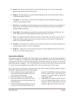
Refer to plate (2) for the following steps.
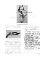
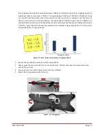
Note that plate (3) only shows one side of the dipole antenna connected to
the BALUN to simplify the detail shown in the photograph.
1.
Attach a Carabiner (h) to the Insulator (g) at the
center end (the end with the Spade Lug), of one
of the 7 MHz Antenna Wires (e).
2.
Attach the Carabiner to the Top Eyebolt (b).
3.
Attach the Insulator at the center end of one of
the 14 MHz Antenna Wires to the Carabiner from
the previous step.
4.
Connect both of the Spade Lugs (f) from steps (1)
and (2) to the same Antenna Connection (c) on
one side of the BALUN (a) by placing a spade lug
around the bolt on each side of the washer,
forming a “V”, as shown in plate (
3). Tighten the
wing nut finger tight.
5.
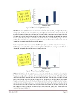
Using a Bowline or similar knot, attach the end of
one of the lengths of Paracord (j) to the end
Insulator on one of the Antenna Wires, as shown
in plate (4). Repeat for the other Antenna wire.


