background image

CHA F-LOOP 3.0 

Page 15 


includes a clutch to prevent damage, you 
should not force the knob past the stops.


4.


Ensure your transmitter is set for no 
more than 5 Watts during tuning.  

5.


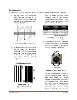
Transmit a carrier and gradually turn the 
Tuning Knob counterclockwise and then 
clockwise,  around  the  highest  receive 
signal point found in step 3, to obtain the 
lowest SWR.  An SWR of 3.0:1 or less is 
satisfactory.    Your  hand  may  slightly 

influence  the  resonance  of  the  loop 
while  turning  the  Tuning  Knob.    This  is 
completely normal, and you may have to 

“touch up”

 the adjustment slightly.  The 

bandwidth  of  the  loop  at  60  meters  is 
only  8  KHz,  so  once  you  are  close  to 
resonance,  make  only  the  slightest  of 
Tuning Knob adjustments. 

6.


Increase transmitter power to no more 
than 25 Watts, see specifications. 


Disassembly 

1.


Disconnect Coaxial Cable and neatly coil cable. 

2.


If used, disconnect Flexible Radiator Loop, carefully coil loop, and secure with attached sticky strap. 

3.


If used, disconnect Flexible Radiator Loop Extension, carefully coil loop, and secure with attached 
sticky strap. 

4.


If used, detach the Flexible Booster Loop and secure pieces with attached sticky straps. 

5.


If used, un-attach the Rigid Radiator Loop.  Re-install the hardware in the Rigid Radiator Loop 
flanges, so they do not get lost. 

6.


Fully collapse Telescoping Mast. 

7.


Remove Coupling Loop from the Telescoping Mast.   

8.


Remove the Telescoping Mast from the Tuning Unit. 

9.


Clean and inspect antenna components and then place them into the Duffel Bag. 

10.


The antenna is now ready for transport and storage. 

 
Troubleshooting 

1.


Ensure the loop is away from metal surfaces.  Sometimes simply reorienting, relocating, or elevating 
the loop around two to four feet higher will reduce the SWR.  

2.


Ensure Radiator Loop Connections are securely tightened.  

3.


Inspect Flexible Radiator Loop for damage.  Replace if damaged. 

4.


Ensure the Coaxial Cable Connection is securely tightened to the Loop Connection. 

5.


Inspect the Coaxial Cable Feedline for cuts in insulation or exposed shielding.  Replace if damaged. 

6.


Ensure Band Switch is set for your frequency range. 

7.


Turn Tuning Knob fully counterclockwise. 

8.


Slowly adjust the Tuning Knob over entire range listening for a marked increase in received signal 
strength and receiver background noise. 

9.


If still not operational, replace the Coaxial Cable Feedline.  

Most problems with antenna systems are 

caused by the coaxial cables and connectors. 

10.


If still not operational, contact us for technical support.   

Summary of Contents for CHA F-LOOP 3.0

Page 1: ...CHA F LOOP 3 0 Page 1 HF Portable Loop Antenna 3 0 CHA F LOOP 3 0 Operator s Manual Nevada USA WWW CHAMELEONANTENNA COM VERSATILE DEPENDABLE STEALTH BUILT TO LAST...

Page 2: ...9 Double Flexible Loop Assembly CHA F LOOP 3 0 BASIC 10 Flexible Booster Loop Assembly CHA F LOOP 3 0 TOTAL 11 Rigid Radiator Loop Assembly CHA F LOOP 3 0 PLUS 12 Power Compensator Installation 13 Lo...

Page 3: ...real practical advantage of the small loop compared to a short vertical whip tuned against earth or a full sized vertical antenna is the loop s freedom from dependence on a ground plane and earth for...

Page 4: ...cause you to mistune the antenna Antennas built by Chameleon AntennaTM are versatile dependable stealthy and built to last Please read this operator s manual so that you may maximize the utility you...

Page 5: ...m Usable Frequency MUF Lowest Usable Frequency LUF and Optimal Working Frequency OWF The MUF is the frequency for which successful communications between two points is predicted on 50 of the days of i...

Page 6: ...NVIS during field testing of the CHA F LOOP 3 0 both DX and NVIS contacts were made on the 30 meter ham band within minutes of each other Parts of the Antenna The CHA F LOOP 3 0 is comprised of the f...

Page 7: ...diameter 146 inch length of shorted coaxial cable with UHF Plugs at both ends and is designed to increase CHA F LOOP 3 0 TOTAL performance in the 60 through 15 meter ham bands f Flexible Radiator Loo...

Page 8: ...del p Rigid Radiator Loop Mounts The Rigid Radiator Loop Mounts are used to attach the Rigid Radiator Loop o to the Tuning Unit a q Telescoping Mast Stud The Telescoping Mast Stud is located on top of...

Page 9: ...following steps to assemble the Standard Single Flexible Loop configuration 1 Select a location to setup the CHA F LOOP 3 0 BASIC antenna The location can be indoors or in an outdoors area protected...

Page 10: ...gle Flexible Loop configuration uses the standard Flexible Radiator Loop Flexible Radiator Loop Extension d and small Coupling Loop included with the CHA F LOOP 3 0 BASIC CHA FLOOP 3 0 PLUS and CHA F...

Page 11: ...he transmitter and observing the SWR meter If used indoors the location should also be reasonably away from switching power supplies Internet routers and other sources of electrical and electronic int...

Page 12: ...the Rigid Radiator Loop Antenna see plate 6 1 Select a location to setup the CHA F LOOP 3 0 PLUS antenna The location can be indoors or in an outdoors area protected from the weather The location must...

Page 13: ...tible antenna mounts available from Chameleon AntennaTM 9 Connect the Coaxial Cable Feedline m to the Loop Connection l 10 Secure the Coaxial Cable Feedline along the Telescoping Mast to ensure easy t...

Page 14: ...antenna configuration Figure 1 Band Switch Label Table 2 shows the more precise frequency range for each antenna configuration and switch setting If the desired operating frequency is in both positio...

Page 15: ...ky straps 5 If used un attach the Rigid Radiator Loop Re install the hardware in the Rigid Radiator Loop flanges so they do not get lost 6 Fully collapse Telescoping Mast 7 Remove Coupling Loop from t...

Page 16: ...ible Booster Loop approximately 4 0 23 1 MHz 60 through 15 meter ham bands Power 25W intermittent duty cycle SSB telephony 10W continuous duty cycle CW AM FM RTTY and other digital modes Diameter 34 i...

Page 17: ...ly any flat surface CHA SPIKE MOUNT The CHA SPIKE MOUNT is an innovative product built exclusively by the skilled machinists at Chameleon AntennaTM It is a precision fabricated heavy duty stainless st...

Page 18: ...Portable Antenna Pioneer References 1 Silver H Ward editor 2013 2014 ARRL Handbook for Radio Communications 91st Edition American Radio Relay League Newington CT 2 1987 Tactical Single Channel Radio...

Reviews: