CHA F-LOOP 3.0
Page 14
Loop Operation
The CHA F-LOOP 3.0 is very easy to use. Perform the following steps whenever you change frequency.
1.
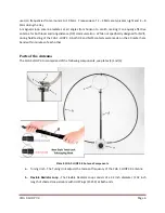
The CHA F-LOOP 3.0 is bidirectional
favoring the sides, see plate (8). If
possible, point one side toward the
target signal and rotate the antenna for
maximum signal strength.
Plate 8. CHA F-LOOP Antenna Directivity.
2.
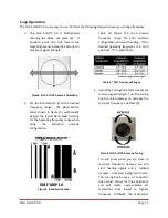
Set the Band Switch (i) to the desired
frequency range. The Band Switch
Label, shown in figure (1), symbolically
depicts the typical Band Switch setting
for the operating frequency range when
using
the
Standard
antenna
configuration.
Figure 1. Band Switch Label.
Table (2) shows the more precise
frequency range for each antenna
configuration and switch setting. If the
desired operating frequency is in both
positions,
“
A
”
is preferrable.
Table 2.
“A/B”
Frequency Ranges.
3.
Adjust the Tuning Knob (h) for maximum
receive signal strength. Turn the Tuning
Knob counterclockwise to decrease the
resonant frequency, see Plate (9).
Plate 9. CHA F-LOOP Antenna Tuning.
You will know when you are close to
resonant frequency because you will
start hearing signals and a marked
increase in receiver background noise.
The Tuning Knob uses a 6:1 reduction
drive which allows for fine adjustment
and will rotate approximately 2¾
revolutions from lowest to highest
frequency. Although the mechanism


