CHA MPAS LITE
Page 6
i.
Spike Mount.
The Spike Mount provides the ground mounted base for the antenna.
j.
Terminal Lug.
The Terminal Lug is located at one end of the Antenna/Counterpoise Wire and used to
connect to the Matching Transformer or Spike Mount.
k.
Insulator Rings.
There are three Insulator Rings, one at each end of the Antenna Wire and one floating in
the center. They are used to mechanically connect and electrically isolate the Antenna Wire.
l.
Shackle.
The Shackle is used to mechanically and electrically attach the Antenna Wire to the Matching
Transformer.
m.
Carabiner.
The Carabiner is used to mechanically connect the Antenna Wire to the Matching Transformer
for strain Relief.
Antenna Configurations
Using the supplied components, the Chameleon Antenna
TM
CHA MPAS LITE antenna can be deployed into two useful
configurations. They are described in this manual and each has unique operational performance characteristics.
Table (2) can assist the operator to quickly select the most appropriate antenna configuration to meet their
operational requirements.
Configuration
Ground Short Medium Long Directionality
End Fed Inverted
“V”
↓
↕
Bi-directional
Telescoping Vertical
↕
↕
Omni-directional
Table 2. Antenna Configuration Selection.
To use the table, decide which distance column (Ground = 0 to 90 miles, Short = 0 - 300 miles, Medium = 300
–
1500
miles, Long > 1500 miles) best matches the distance to the station with whom you need to communicate. Then,
determine if the OWF is in the l
ower (↓ = 1.8 –
10 MHz) or upper (↑ = 10 –
30 MHz) frequency range. Finally, select
the CHA MPAS LITE configuration with the corresponding symbol in the appropriate distance column. Both CHA
MPAS LITE configurations provide some capability in each distance category, so depending upon the complexity of
your communications network, you may need to select the best overall configuration. The directionality column
indicates the directionality characteristic of the antenna configuration. When using NVIS, all the configurations are
omnidirectional.
End Fed Inverted
“V”
Configuration
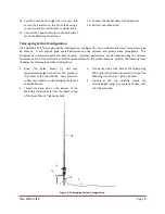
The CHA MPAS LITE, End Fed Inverted
“V”
configuration, see figure (1), is a short to medium range HF antenna. It
can provide good medium range communication on all HF frequencies and acceptable NVIS propagation below 10
MHz. This configuration is bi-directional broadside to the antenna above 10 MHz and omni-directional below 10
MHz. Improved performance can be obtained using at least one counterpoise from the optional Counterpoise Kit.
Perform the following steps to deploy the End Fed Inverted “V” configuration.

