background image

CHA MPAS LITE 

Page 9 


5.


Connect  the  Terminal  Lug  (j)  at  the  end  of  the 
Counterpoise  Wire  (f)  to  the  Counterpoise 
Connection (d) on the Spike Mount. 

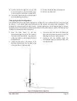
The  antenna  base  should  look  like  that  pictured  in 
plate (4). 

6.


Unwind around 25 feet of the Counterpoise Wire 
from the Line Winder (b).   

7.


Extend the Counterpoise Wire in any convenient 
direction.    Lay  the  Line  Winder  with  unwound 
Counterpoise Wire on the ground. 

8.


Connect  the  Coaxial  Cable  Assembly  (k)  to  the 
UHF Socket (e) on the Matching Transformer. 

9.


Connect the Coaxial Cable to the Radio Set. 

10.


Perform operational test. 


Plate 4.  Telescoping Vertical Base. 


Recovery Procedure 

To recover the CHA MPAS LITE antenna, perform the following steps: 
1.


Disconnect the Coaxial Cable from the radio set. 

2.


Disconnect the Coaxial Cable from the Matching Transformer. 

3.


Carefully roll (do not twist) the Coaxial Cable.  Secure the rolled cable with a sticky strap and set aside. 

4.


If used, detach the Telescoping Whip and starting from the bottom, collapse one section at a time until the 
Telescoping Whip is completely collapsed. 

5.


Disconnect the Antenna/Counterpose Wire. 

6.


Wind the Antenna/Counterpoise Wire onto the Line Winder and secure with attached shock cord. 

7.


Detach the Matching Transformer. 

8.


Pull the Spike Mount out of the ground. 

9.


Remove dirt from antenna components and inspect them for signs of wear. 

10.


Store components together ready for next antenna deployment. 


Troubleshooting 

1.


Inspect the Antenna/Counterpoise Wire for breakage or signs of strain. 

2.


Inspect the Telescoping Whip for breakage. 

3.


Ensure UHF Plug from the Coaxial Cable Assembly is securely connected to the UHF Socket of the Matching 
Transformer and Radio Set. 

4.


Inspect Coaxial Cable Assembly for cuts in insulation or exposed shielding. 

5.


If still not operational, replace Coaxial Cable Assembly.  

Most problems with antenna systems are caused by 

the coaxial cables and connectors. 

6.


If still not operational, contact Chameleon Antenna

TM  

at 

support@chameleonantenna.com

 for technical 

support, be sure to include details on the antenna configuration, symptoms of the problem, and what steps 
you have taken. 


Summary of Contents for CHA MPAS LITE

Page 1: ...Modular Portable Antenna System MPAS Lite Operator s Manual Nevada USA WWW CHAMELEONANTENNA COM VERSATILE DEPENDABLE STEALTH BUILT TO LAST...

Page 2: ...ect you Stay away from all power lines WARNING Never operate this antenna where people could be subjected to high levels of RF exposure especially above 10 watts or above 14 MHz Never use this antenna...

Page 3: ...MICRO allows broadband antenna tuning The antenna will operate continuously from 1 8 54 0 MHz including 160m 6m amateur bands without any adjustment with a wide range antenna tuner or coupler when usi...

Page 4: ...most important thing for the operator to understand about HF radio wave propagation is the concept of Maximum Usable Frequency MUF Lowest Usable Frequency LUF and Optimal Working Frequency OWF The MUF...

Page 5: ...rpoise Connection The Counterpoise Connection is the red knurled knob on the side of the Spike Mount used to connect the Counterpoise Wire e UHF Socket The UHF Socket SO 239 is located on the side of...

Page 6: ...tical Omni directional Table 2 Antenna Configuration Selection To use the table decide which distance column Ground 0 to 90 miles Short 0 300 miles Medium 300 1500 miles Long 1500 miles best matches t...

Page 7: ...ly eight inches into the ground Use a plastic or rubber tent mallet to avoid damaging the face of the Spike Mount 6 Thread the stud at the base of the Matching Transformer a into the socket on top of...

Page 8: ...performance can be obtained using the optional Counterpoise Kit which will create an efficient ground plane for the vertical antenna Perform the following steps to deploy the Telescoping Vertical con...

Page 9: ...om the bottom collapse one section at a time until the Telescoping Whip is completely collapsed 5 Disconnect the Antenna Counterpose Wire 6 Wind the Antenna Counterpoise Wire onto the Line Winder and...

Page 10: ...l Clamp Mount is the first ham radio antenna mounting system purposely designed for extreme portable operations This is a rugged robust product intended to support considerable antenna loads Specifica...

Page 11: ...CHA MPAS LITE Page 11 Figure 4 End Fed Inverted V Far 80m Field Plot Figure 5 End Fed Inverted V 40m Far Field Plot...

Page 12: ...p for a period of 12 months from the date of purchase To obtain warranty service return all components of the system to Chameleon Antenna at your expense Chameleon Antenna will repair or replace defec...

Page 13: ...Portable Antenna Pioneer References 1 Silver H Ward editor 2013 2014 ARRL Handbook for Radio Communications 91st Edition American Radio Relay League Newington CT 2 1987 Tactical Single Channel Radio...

Reviews: