CHA RXL
Page 10
Table Top Installation.
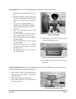
Peel off the adhesive backing on each of the Rubber Feet and stick one in
each corner of the Mounting Plate on the bottom of the Preamplifier Unit (b). The CHA RXL can be
placed on a table top or other flat surface inside your building. Performance of the CHA RXL may be
degraded by the building construction material or proximity to interior sources of Radio Frequency
Interference (RFI).
Other Mounting Options.
Chameleon Antenna
TM
sells an optional adapter (CHA SS ADAPTER) that converts
the ¼” X 20 camera tripod mount to a 3/8” X 24 antenna mount. Using this adapter, you can mount the CHA RXL
on any of the optional
Chameleon Antenna
TM
antenna mounts, such as the Universal Clamp Mount (CHA UCM).
Connecting the Receive Loop Antenna.
Perform the following procedure to connect the CHA RXL to your LF/MF/HF Radio Receiver.
1.
Connect one end of the Coaxial Cable
(not
supplied)
to the Remote Antenna Connection (c)
on the Preamplifier Unit (b).
2.
Connect the other end of the Coaxial Cable to the
Local Antenna Connection (m) on the BIAS-T Unit
(j).
Because the BIAS-T supplies 12V DC power to the
Loop Preamplifier through the Coaxial Cable, do not
install any other electrical device, such as an
antenna switch, duplexer, rotor controller, etc.
between the BIAS-T Unit and the Loop Preamplifier.
3.
Connect one end of a Coaxial Jumper Cable
(not
supplied)
to the Radio Connection (m) on the
BIAS-T Unit.
4.
Connect the other end of the Coaxial Jumper
Cable to the Radio Receiver.
5.
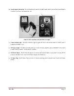
Connect the DC Power Plug (q) to the DC Power
Socket (o) on the BIAS-T Unit (j).
6.
Plug the DC Power Supply (p) into 120V AC
electrical outlet. The Power Indicator Light (n)
will illuminate green.
7.
Perform an operational test.
IMPORTANT: This is a RECEIVE-ONLY antenna -
DO NOT TRANSMIT using this antenna, as doing
so will permanently
damage the electronic
preamplifier!
The Receive Loop must be installed a minimum
of 25 feet from other antennas in use by
transmitters transmitting 100 Watts or more.
Troubleshooting
1.
Ensure the Power Indicator Light is illuminated green. Replace Power Supply if Power Indicator Light is not
illuminated. If the problem is not resolved by replacing the Power Supply, replace the BIAS-T Unit.
2.
Ensure Loop Flange connections are securely tightened.
3.
Ensure all Coaxial Cable Connections are securely tightened.
4.
Inspect Coaxial Cable and Coaxial Jumper Cable for cuts in insulation, exposed shielding, or loose connectors.
Replace if damaged.
Most problems with antenna systems are caused by the coaxial cables and connectors.
5.
If still not operational, contact us for technical support at

