CHA SKYLOOP
(updated February, 2020)
Page 5
e.
Isolation Loop.
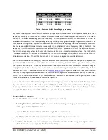
Five Isolation Loops are permanently attached to the Antenna Wire and are used to suspend
three corners of the loop and as insulators at the feedpoint.
Plate 1
.
CHA SKYLOOP Antenna.
f.
Wire Connector.
The Wire Connectors are located at each end of the Antenna Wire.
g.
Ground Connection.
The Ground Connection is located on the bottom of the Matching Transformer (a) and
provides an optional electrical ground for lightning protection.
h.
UHF Socket.
The UHF Socket, SO-239, is located on the bottom of the Matching Transformer.
i.
Transformer Eyebolt.
The Transformer Eyebolt is located on the top of the Matching Transformer.
j.
Antenna Connection.
The two Antenna Connections are located on the top of the Matching Transformer and
are used to attach the Wire Connectors (f).
k.
Support Line.
The Support Line
(not included)
is Polyester or Nylon abrasion-resistant rope used to suspend
the antenna from the necessary supports.
SKYLOOP Installation
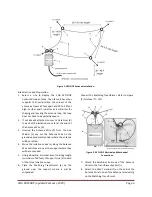
The CHA SKYLOOP, see figure (1), is installed horizontally and requires four supports at least 64 feet apart that, when
the antenna wire is suspending from them, will form the CHA SKYLOOP approximately in the shape of a square. The
supports should also be 30 to 40 feet high, although heights as low as 10 feet will work, but with reduced
performance. An optional electrical ground wire may be used for lightning protection. The coaxial cable should be at
least 25 in length.

