background image

201162 - 4000 Lb. (1,814 KG) WiNch

ASSEMbLY

10

contactor/Solenoid Location

Find a location for the contactor/solenoid. It is 
recommended that the contactor/solenoid be mounted 
close to the battery in a clean, dry location. Make sure 
the location chosen allows for sufficient clearance from 
all metal components. Drill mounting holes if required. 
Once a location is found, DO NOT install the unit until all 
wiring is completed (see wiring section).

 

NOTicE

Terminals coming in contact with metal will cause a 
direct short, possibly causing contactor/solenoid and/
or battery damage.

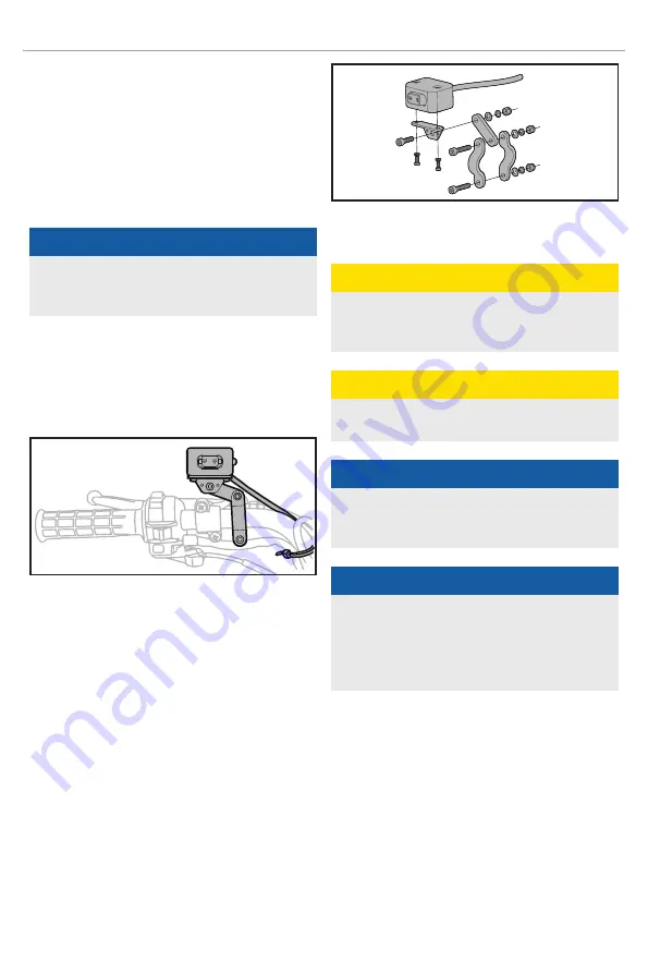
installing the Mini-Rocker Switch

1.  Decide which handlebar the mini-rocker switch will 

be mounted on. The mini-rocker switch is usually 
installed on the left handlebar.

2.  Use a piece of electrical tape (not provided) around 

the handlebar to help prevent rotation of the mount.

Loosen the hardware and mount to the handlebar.

Tighten the mini-rocker switch in place. DO NOT 
overtighten or tighten/clamp over any hoses or 
cables.

Once the mini-rocker switch is mounted, the wires 
can be routed back to where the solenoid/contactor 
is located.

Make sure the handlebars have full range of motion 
and then secure the mini-rocker switch’s cable with 
the supplied cable ties.

Wiring the Winch

 

cAUTiON

NEVER

 route electrical cables across any sharp 

edges, through and/or near moving parts, or near 
parts that may become hot.

 

cAUTiON

Battery cables should NOT be drawn tight. Leave 
some slack for cable movement.

 

NOTicE

You may need to use a test light to locate a suitable 
wire. The wire should only have power when the key is 
in the ON position.

 

NOTicE

Depending on the location of the solenoid/contactor, 
you may need to use the black and red cables in place 
of the yellow and blue, and the yellow and blue in 
place of the red and black. Just remember that this 
also changes the diagram.

1.  Connect the yellow and blue cables to the motor 

terminals on the winch. (Yellow to the positive 
(+) terminal of the motor. Blue to the negative (-) 
terminal of the motor). Tighten the terminal nuts 
on the motor. DO NOT over tighten. Route the other 
ends to the solenoid/contactor location.

2.  Connect the yellow and blue cables to the solenoid/

contactor (yellow to yellow and blue to blue). 
DO NOT tighten nuts.

Summary of Contents for 201162

Page 1: ...ing the product Failure to do so could result in serious injury This manual should remain with the product Specifications descriptions and illustrations in this manual are as accurate as known at the...

Page 2: ...ssembly 9 Assembling the Winch 9 Contactor Solenoid Location 10 Installing the Mini Rocker Switch 10 Wiring the Winch 10 Test Winch Operation 11 Wiring Diagram 12 Switch Wiring Diagram 12 Operation 13...

Page 3: ...s exercise common sense and always err on the side of caution when operating the product to ensure no accident property damage or injury occurs We want you to continue to use and be satisfied with you...

Page 4: ...ook strap when handling the hook for spooling or unspooling the cable rope CAUTION Always use gloves to protect hands when handling the cable rope Never let the cable rope slide through your hands WAR...

Page 5: ...udy them and learn their meaning Proper interpretation of these symbols will allow you to more safely operate the product Symbol Meaning Turn the clutch to the IN position to retract the rope Turn the...

Page 6: ...n feed or wind the cable rope depending on the remote winch switch 4 Cable Rope 7 32 in 49 ft 5 4 mm 15 m galvanized aircraft cable designed specifically for load capacity of 4000 lb 1814 kg 5 Braking...

Page 7: ...Power from the vehicle battery flows through the weather sealed contactor before being directed to the winch motor 12 Mounting Channel Winch mount to attach the winch to your vehicle 13 Winch Connect...

Page 8: ...1 Lock Washer 10 2 Lock Nut M10 2 1x 16mm wrench or socket Mini Rocker Switch 1 Hexagon Socket Head Screw M5 x 18 1 1x 4mm allen wrench 2 2 3 3 4 Hexagon Socket Head Screw M5 x 25 2 1x 4mm allen wren...

Page 9: ...M8 25 F bolts through the 8 lock G and flat washers H and then thread through the mounting channel Tighten the bolts DO NOT overtighten F H G 4 Turn winch right side up Disengage the clutch by moving...

Page 10: ...tch is mounted the wires can be routed back to where the solenoid contactor is located Make sure the handlebars have full range of motion and then secure the mini rocker switch s cable with the suppli...

Page 11: ...proper drum rotation Turn the clutch to the Out position free spooling Pull out some cable from the drum and then turn the clutch to the In position to engage the gears Out Clutch In With some applic...

Page 12: ...201162 4000 lb 1 814 KG Winch Assembly 12 Wiring Diagram Blue Yellow Black Positive Positive Negative Switch Wiring Diagram Black Green Red Ignition Wire Solenoid Contactor Battery Black Green Red...

Page 13: ...shall be replaced immediately Use only manufacturer s identical replacement cable rope with the exact specifications Inspect the winch installation and bolts to ensure that all bolts are tight before...

Page 14: ...l connections are secure m Inspect the cable rope Make sure there are at least 5 wraps of cable rope around the winch drum Your rope is marked with red on wrap 5 to 6 as a visual indicator Red n Clear...

Page 15: ...1 877 338 0999 Lubrication All moving parts within the electric winch have been lubricated using high temperature lithium grease at the factory No internal lubrication is required Lubricate rope assem...

Page 16: ...h while re spooling Turn off the winch and repeat the procedure until a few feet of cable rope are left Disconnect the mini rocker switch and finish spooling by rotating the drum by hand with the clut...

Page 17: ...3000 4000 kg 0 454 907 1361 1814 Line Speed 12V DC FPM 12 8 11 5 8 9 6 2 3 3 MPM 3 9 3 5 2 7 1 9 1 3 Motor Current 12 V DC A 28 90 150 200 220 Run Time Minutes 1 1 1 1 1 Cooling Time Minutes 5 5 5 5...

Page 18: ...short burst with load until completely dry Motor runs but drum does not turn Clutch cam ring not engaged Move cam ring to the In position If problem persists a qualified technician needs to check and...

Page 19: ...product is deemed to have been misused neglected involved in an accident abused loaded beyond the product s limits modified installed improperly or connected incorrectly to any electrical component N...

Reviews: