background image


20

92050-1


ENGLISH

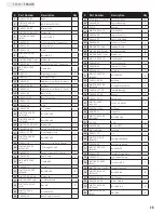
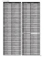
# Part Number

Description

Qty

41

ASME B18.2.1 1996

Bolt 5/16"-24

×

1"

4

42

PMJ22G-29

Engine Bushing

1

43

26.110

Engine

1

44

GB/T 1096-1979

Flat Key 5x5

1

45

PMJ22G-28

Engine Connector

1

46

PMJ22G-27

Gear Pump Stand

1

47

PMJ22G-32

Connector Cover

1

48

GB/T 845C-1985

Tapping Screw

4

49

GB/T 848-1985 (ø4)

Lock Washer ø4

4

50

GB/T 859-1987 (ø4)

Washer ø4

4

51

GB/T 1099-1979

Flat Key 3x3

1

52

PMJ22Q-22

Filter Connector

1

53

PMJ22Q-20

Internal Oil Filter

1

54

PMJ22G-19

Oil Plug

1

55

GB/T 5782-2000 
(M8

×

45)

Bolt M8

×

45

4

56

PMJ22J-05-02

Axle Cap

2

57

GB/T 9459-1988 
(M20x1.5)

Slotted Nut M20x1.5

2

58

L44634 LYC DS

Tapered Bearing

4

59

PMJ22D-05-03

Wheel

2

60

PMJ22J-05-01

Cased Seal

2

61

GB/T 91-2000 
(ø4

×

32)

Cotter Pin ø4

×

32

2

62

PMJ22M-01-00

Oil  Tank

1

63

PMJ22G-12

Hinge Pin

1

64

GB/T 5782-2000 
(M12

×

85)

Bolt M12

×

85

2

65

GJY12-3

R Pin

1

66

PMJ22G-18

Screw NPT1"

1

67

GB 1160.2-89

Oil Scale

1

68

PMJ22J-15

Pin

1

69

GB/T 798-1988 
(M8x28)

Swing Bolt M8x28

1

70

PMJ22G-38

Big Tension Spring

1

71

GB/T 5783-2000 
(M8

×

20)

Bolt M8

×

20

4

72

PMJ22J-03

Cylinder Fixing Plate

2

73

PMJ30F-01-Y

Log Catcher-Yellow

2

74

GB/T 889.1-2000 
(M10)

Lock Nut M10

1

75

GB/T 93-1987 (ø10)

Lock washer ø10

12

76

GB/T 5781-2000 
(M10x15)

Bolt M10x15

8

77

PMJ22G-34-00

Left  Fender

1

78

PMJ22G-35-00

Right  Fender

1

79

GB/T 5781-2000 
(M10x25)

Bolt M10x25

4

80

GB/T 6170-2000 
(M10)

Nut M10

4

# Part Number

Description

Qty

1

PMJ22J-02-00

Beam

1

2

GB/T 5782-2000 
(M12

×

75)

BOLT M12

×

75(12.9)

1

3

PMJ22J-04-00

Wedge Slide

1

4

GB/T 95-2000 (ø12)

Washer ø12

7

5

GB/T 889.1-2000 
(M12)

Lock Nut M12

7

6

PMJ22G-51

Control Valve "IN" Connector

1

7

PMJ22J-12

Control Valve

1

8

PMJ22J-19

Plate

1

9

GB/T 818-2000 
(M8x12)

Bolt M8x12

2

10

GB/T 859-1987 (ø8)

Washer ø8

2

11

PMJ22G-49

Control Valve "OUT" Connector

2

12

JB/T 8870-1999 
(d25)

Clamp d25

2

13

PMJ7-15

Right Angle Joiner

2

14

PMJ7-22

Through Joiner

1

15

PMJ22Q-21

Hydraulic Hose(Valve-Cylinder)

1

16

PMJ22Q-08-00

Cylinder

1

17

PMJ22G-15

Hydraulic Hose(Valve-Oil Tank)

1

18

PMJ22J-06

Base Tube

1

19

PMJ23-01-00

Base Connector

1

20

PMJ22J-10

Pin

1

21

PMJ22G-30

R Pin

2

22

PMJ22G-40

2" Coupler

1

23

GB/T 5782-2000 
(M12

×

80)

Bolt M12

×

80

2

24

GB/T 5782-2000 
(M10

×

85)

Bolt M10

×

85

1

25

GB/T 95-2000 (ø10)

Washer ø10

16

26

PMJ25M-18-00

Safety Chain With Hook

2

27

PMJ22J-07-00

Front Support Leg

1

28

GB/T 5782-2000 
(M12

×

65)

Bolt M12

×

65

2

29

PMJ22J-18

Hydraulic Hose(Valve-Pump)

1

30

GB/T 3452.1-92 
(ø10

×

2.65)

"O" Ring ø10

×

2.65

1

31

PMJ22G-21

Outlet Connector Of Pump

1

32

PMJ22G-42

Gear Pump

1

33

JB/T 8870-1999 
(d40)

Clamp d40

2

34

PMJ22G-17

Oil Pipe

1

35

GB/T 5783-2000 
(M8

×

30)

Bolt M8

×

30

4

36

GB/T 95-2000 (ø8)

Washer ø8

16

37

GB/T 93-1987 (ø8)

Lock Washer ø8

16

38

GB/T 6170-2000 
(M8)

Nut M8

9

39

GB/T 77-2000 
(M6

×

10)

Screw M6

×

10

1

40

PMJ22G-26

Gear Pump Connector

1

Summary of Contents for 92050-1

Page 1: ...TER 12039 Smith Ave Santa Fe Springs CA 90670 USA 1 877 338 0999 www championpowerequipment com SAVE THESE INSTRUCTIONS Important safety instructions are included in this manual MADE IN CHINA REV 92050 1 20170520 92050 1 MODEL NUMBER ...

Page 2: ...N IMPORTANT MESSAGE ABOUT TEMPERATURE Your Champion Power Equipment product is designed and rated for continuous operation at ambient temperatures up to 40 C 104 F When your product is needed your product may be operated at temperatures ranging from 15 C 5 F to 50 C 122 F for short periods If the product is exposed to temperatures outside this range during storage it should be brought back within ...

Page 3: ...he Log Splitter 13 Towing Log Splitter Safety 13 Log Splitter Location 13 Starting the Engine 14 Stopping the Engine 14 Log Splitter Operation 15 Operation at High Altitude 15 Maintenance and Storage 16 Engine Maintenance 16 Oil 16 Spark Plugs 16 Air Filter 16 Cleaning 16 Maintenance Schedule 17 Log Splitter Maintenance 17 Storage 17 Log Splitter Storage 17 Engine stored for Less than 30 Days 17 E...

Page 4: ...re the accuracy and completeness of the information in this manual and we reserve the right to change alter and or improve the product and this document at any time without prior notice Since CPE CET highly value how our products are designed manufactured operated and are serviced and also highly value your safety and the safety of others we would like you to take the time to review this product m...

Page 5: ...ifferent kinds of information The safety symbol is used with a key word to alert you to potential hazards in operating and owning power equipment Follow all safety messages to avoid or reduce the risk of serious injury or death DANGER indicates an imminently hazardous situation which if not avoided will result in death or serious injury DANGER WARNING indicates a potentially hazardous situation wh...

Page 6: ...uld result in serious injury or death WARNING Before removing the pin installed into the front support leg make sure hitch is installed onto vehicle Releasing the pin before will cause support leg to slide up and possibly cause injury WARNING Sparks can result in fire or electrical shock DANGER When servicing the engine Disconnect the spark plug wire and place it where it cannot contact the plug D...

Page 7: ...ug wire When storing the log splitter Store away from sparks open flames pilot lights heat and other sources of ignition DANGER SAFETY RULES Skin injection hazard High pressure hydraulic oil can inject under your skin DANGER Make sure all fittings are tightly secure before applying pressure Relieve system of pressure before servicing Towing hazard ALWAYS check all local and state regulations regar...

Page 8: ...once Serious infection or reaction can develop if proper medical treatment is not administered immediately 8 Keep the operator zone and adjacent area clear for safe secure footing 9 If your log splitter is equipped with an internal combustion engine and intended for use near any unimproved forest brush or grass covered land the engine exhaust should be equipped with a spark arrestor Make sure you ...

Page 9: ... It is possible for connections to vibrate loose over time 3 Never leave the machine unattended with the power source operating 4 Never operate the machine when under the influence of alcohol drugs or medication 5 The machine owner should instruct all operators in safe log splitter operation 6 Always operate the log splitter with all safety equipment in place and all controls properly adjusted for...

Page 10: ...Splitting Beam 7 Log Catchers 8 Fenders 9 Tires Maximum travel speed is 72 km h 45 MPH 10 Mounting Plates Holds hydraulic cylinder in place 11 Support Leg Supports log splitter while operating Raise leg for towing 12 Safety Chains For use while towing Log Splitter CONTROLS AND FEATURES Read this owner s manual before operating your log splitter Familiarize yourself with the location and function o...

Page 11: ... the hub 3 Slide the wheel over the axel on the hydraulic oil tank 4 Install the castle nut and tighten by hand Tighten another turn with a wrench to seat the bearing 5 Spin the wheel to distribute grease 6 Loosen the castle nut and re tighten by hand 7 Install the cotter pin through the castle nut and axle to prevent the nut from backing off 8 Place axle cap over castle nut and axle 9 Repeat step...

Page 12: ...the way back into the mounting slots NOTE 4 Secure the cylinder mounting plates with hardware removed in step 2 B 5 Slide the wedge back toward the cylinder and align the bolt hole in the wedge with the bolt hole in the cylinder rod B 6 Secure the wedge to the cylinder rod with an M12x75 bolt and M12 nut Lightly tighten the nut to approximately 5 ft lb B B The cylinder rod may need to be rotated s...

Page 13: ... the hydraulic oil tank just beneath the engine and the other end to the pump inlet on the bottom of the pump C C B A D 1 Attach log catcher 1 to side of beam with four M10x15 bolts 2 four M10 lock washers 3 and four M10 washers 4 2 Repeat step 1 for the other side 7 Install the Log Catchers Red shipping plugs must be removed from hydraulic pump prior to installing hoses Hydraulic pump may contain...

Page 14: ... period change the oil NOTE Once oil has been added a visual check should show oil about 1 2 threads from running out of the fill hole If using the dipstick to check oil level DO NOT screw in the dipstick while checking NOTE Weather will affect engine oil and engine performance Change the type of engine oil used based on weather conditions to suit the engine needs NOTE Add Engine Oil 1 Make sure t...

Page 15: ...r hand while the system is pressurized Seek medical attention immediately if injured by escaping fluid WARNING Add Hydraulic Oil 1 Make sure the log splitter is on a flat level surface 2 Remove the oil plug from the oil tank A 3 Add 15 1 L 4 gal of hydraulic oil 10W AW32 ASLE H 150 or ISO 32 are all acceptable types of fluid 4 Check the hydraulic oil level using the oil sight glass Oil level shoul...

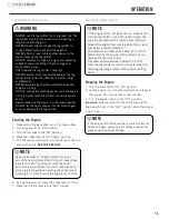
Page 16: ...injury or death Always adjust your towing speed according to the terrain and conditions 4 Always disconnect the log splitter from the towing vehicle before operating Log Splitter Location This log splitter must have at least 2 1 m 7 ft of clearance from combustible material Leave at least 91 4 cm 3 ft of clearance on all sides of the log splitter to allow for adequate cooling maintenance and servi...

Page 17: ...let the beam drop as it could crush fingers or cause damage to the log splitter WARNING Log Splitter Location Cont d Starting the Engine Cont d If the engine starts but does not run make certain that the log splitter is on a flat level surface The engine is equipped with a low oil sensor that will prevent the engine from running when the oil level falls below a critical threshold The hydraulic oil...

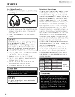
Page 18: ...be changed by adjusting the engine At high altitudes increased exhaust emissions can also result due to the increased enrichment of the air fuel ratio Other high altitude issues can include hard starting increased fuel consumption and spark plug fouling To alleviate high altitude issues other than the natural power loss Champion Power Equipment can provide a high altitude carburetor main jet The a...

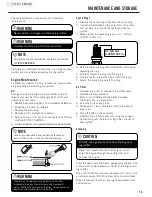
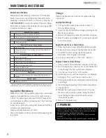
Page 19: ...r CAUTION Water can contaminate the fuel system and can enter the engine through the cooling slots and damage the engine Cleaning Clear the debris from the beam wedge and endplate Use a damp cloth to clean exterior surfaces of the engine and log splitter Use a soft bristle brush to remove excess dirt and oil Use an air compressor 25 PSI to clear dirt and small debris Wipe all metal parts with an o...

Page 20: ...r before storage according to the Maintenance section 3 Retract the wedge to protect the rod from corrosion 4 Wipe the beam and wedge with an oily rag to prevent rust and corrosion Engine Stored for Less than 30 Days 1 Allow the engine to cool completely before storage 2 Clean engine according to the Maintenance section 3 To extend the fuel storage life add a properly formulated fuel stabilizer to...

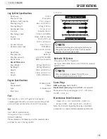
Page 21: ...ear Pump 2 stage Max pressure 3600 psi Max flow capacity 30 3 LPM 8 GPM Control Valve Detent auto return Overall Dimensions Gross Weight 200 kg 440 9 lb Net Weight 180 kg 396 8 lb Height 116 5 cm 45 9 in Width 103 5 cm 40 7 in Length 218 cm 85 8 in Spark Plugs OEM spark plug NHSP F6RTC Replacement spark plug NGK BPR6ES or equivalent Make certain the spark plug gap is 0 7 0 8 mm or 0 028 0 031 in H...

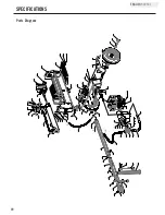
Page 22: ... 4 5 28 19 24 20 21 26 27 23 22 5 25 30 31 32 33 34 33 47 48 46 42 44 43 40 39 49 52 54 12 11 64 59 58 60 58 57 56 61 18 62 5 TO A A TO B TO C TO D B C D 65 55 4 TO E E Parts Diagram TO F F 41 37 36 35 36 37 38 38 37 36 71 36 37 72 9 70 69 38 67 10 8 13 29 53 14 73 25 75 76 77 78 79 80 75 25 45 74 ...

Page 23: ...5 00 Right Fender 1 79 GB T 5781 2000 M10x25 Bolt M10x25 4 80 GB T 6170 2000 M10 Nut M10 4 Part Number Description Qty 1 PMJ22J 02 00 Beam 1 2 GB T 5782 2000 M12 75 BOLT M12 75 12 9 1 3 PMJ22J 04 00 Wedge Slide 1 4 GB T 95 2000 ø12 Washer ø12 7 5 GB T 889 1 2000 M12 Lock Nut M12 7 6 PMJ22G 51 Control Valve IN Connector 1 7 PMJ22J 12 Control Valve 1 8 PMJ22J 19 Plate 1 9 GB T 818 2000 M8x12 Bolt M8...

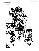
Page 24: ... 44 45 46 47 48 49 50 51 52 53 54 55 56 57 58 59 60 61 62 63 64 65 66 67 68 69 70 71 72 73 74 76 77 78 79 80 81 82 83 84 85 86 87 88 89 90 91 92 93 94 95 96 97 98 100 101 102 103 104 105 106 107 108 109 110 111 112 113 114 115 117 118 122 123 79 99 124 125 126 127 128 129 130 132 133 134 135 136 11 75 19 112 79 99 112 11 42 1 31 131 121 120 119 108 29 30 116 20 11 ...

Page 25: ...40002 00 Valve Intake 1 66 23 040006 00 Valve Exhaust 1 67 26 080400 00 Air Guide Lower 1 68 2 15 002 F6RTC Spark Plug F6RTC 1 Part Number Description Qty 69 1 5789 0855 Flange Bolt M8 55 4 70 23 040017 00 Oil Seal Valve 2 71 21 040003 00 Spring Valve 2 72 21 040007 00 Retainer Exhaust Valve Spring 1 73 21 040001 00 Retainer Intake Valve Spring 1 74 21 040008 00 Rotator Exhaust Valve 1 75 24 04020...

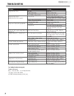
Page 26: ...a Wedge movement is slow or erratic Air in the hydraulic oil system Purge air by extending and retracting the wedge several times until motion is smooth Debris lodged in beam guides Clear debris from beam Low hydraulic oil Check oil level and add as needed Oil leak from hose connection Loose hose clamp or hydraulic fitting Tighten hose clamp or hydraulic fitting Oil leak from cylinder Faulty cylin...

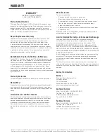
Page 27: ...trical component Normal maintenance is not covered by this warranty and is not required to be performed at a facility or by a person authorized by CPE Other Exclusions This warranty excludes Cosmetic defects such as paint decals etc Wear items such as filter elements o rings etc Accessory parts such as starting batteries and storage covers Failures due to acts of God and other force majeure events...

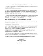
Page 28: ...trol system is warranted for two years subject to provisions set forth below If during the warranty period emission related part on your engine is defective in materials or workmanship the part will be repaired or replaced by CPE OWNER WARRANTY RESPONSIBILITIES As the small off road engine owner you are responsible for the performance of the required maintenance listed in your Owner s Manual CPE r...

Page 29: ...all be warranted for the remainder of the ECS Warranty Period c Any warranted emissions related part which is scheduled for replacement as required maintenance in the Owner s Manual shall be warranted for the period of time prior to the first scheduled replacement point for that part If the part fails prior to the first scheduled replacement the part shall be repaired or replaced by CPE according ...

Page 30: ...separator carbon canister canister mounting brackets carburetor purge port connector TO OBTAIN WARRANTY SERVICE You must take your CPE engine or the product on which it is installed along with your warranty registration card or other proof of original purchase date at your expense to any Champion Power Equipment dealer who is authorized by Champion Power Equipment Inc to sell and service that CPE ...

Reviews: