background image


Specifications 


19


Parts List 

No. 

Item # 

Description 

Qty 

Engine 

1 GF2.041105.01.10-1 

Throttle Return Spring 

2 GF2.041105.01.10-2 

Governor Rod 

3 GF2.041105.01.10-3 

Governor 

Arm 

4 GF2.041105.01.10-4 

Governor 

Spring 

5 GB/T6177 

Nut 

M6 

6 GF2.041105.01.10-5 

Lock 

Pin 

GF2.041105.01.10-6 

Governor Arm Washer 

GF2.041105.01.10-7 

Snap Ring 8 

GB/T896 

Governor Arm Shaft 

10 GF2.041105.01.10-8 

Governor Support 

11 GB/T5789 

Bolt 

M6*12 

17 

12 GB/T5789 

Bolt 

M6*8 

13 

GF2.011105.01.13-5 

Recoil Starter Knob 

14 

GF2.041105.01.13-01 

Recoil Starter Complete 

15 

GF2.041105.01.13-2 

Recoil Starter Spring 

16 

GF2.041105.01.13-3 

Recoil Starter Rope 

17 

GF2.041105.01.13-4 

Recoil Starter Reel 

18 GF2.041105.01.13-5 

Ratchet 

Spring 

19 GF2.041105.01.13-6 

Starter 

Ratchet 

20 GF2.041105.01.13-7 

Ratchet 

Guide 

21 GF2.041105.01.13-8 

Ratchet 

Guide 

Bolt 

22 GF2.041105.01.13-02 

Fan 

Cover Complete 

23 GF2.041105.01.00-6 

Nut 

24 GF2.041105.01.00-7 

Starter 

Hub 

25 GF2.041105.01.14-1 

Cooling 

Fan 

26 GF2.041105.01.14-01 

Fly 

Wheel 

27 GF2.041105.01.01-01 

Oil 

Seal 

28 GB/T5789 

Bolt 

M6*25 

29 GF2.041105.01.15-02 

Ignition 

30 GF2.041105.01.01-6 

Dowel 

Pin 

31 GF2.041105.01.00-13 

Bolt 

M8*55 

32 

GF2.041105.01.01-9 

Oil Drain Plug 

33 

GF2.041105.01.01-8 

Oil Drain Plug Washer 

34 GF2.041105.01.15-02 

Signal 

Magnifier 

35 GF2.041105.01.01-5 

Crankcase 

Assembly 

36 

GF2.041105.01.01-03 

Radial Ball Bearing6202/P6 

37 

GF2.041105.01.15-03 

Oil Level Switch Assembly 

38 GF2.041105.01.10-9 

Governor Weight Holder 

39 

GF2.041105.01.10-10 

Governor Weight Pin 

40 GF2.041105.01.10-11 

Governor 

Shaft 

41 

GF2.041105.01.10-12 

Governor Shaft Clip 

42 GF2.041105.01.10-13 

Governor Weight 

43 GF2.041105.01.10-14 

Governor 

Shaft 

Washer 

44 GF2.041105.01.10-15 

Governor 

Slider 

45 GF2.041105.01.03-01 

Crankshaft Complete 

46 GF2.041105.01.01-7 

Crankcase 

Packing 

47 GF2.041105.01.01-1 

Oil 

Filler Cap Assembly 

48 GF2.041105.01.01-2 

Oil 

Filler Cap Packing 

49 GF2.041105.01.01-3 

Crankcase 

Cover 

50 GB/T5789 

Bolt 

8*32 

51 

GF2.041105.01.11-02 

Air Cleaner Cover Complete 

52 

GF2.041105.01.11-1 

Air Cleaner Element 

53 

GF2.041105.01.11-2 

Air Cleaner Grid 

54 

GF2.041105.01.11-3 

Air Cleaner Seal 

Summary of Contents for C75520

Page 1: ...Capacity 10 Power Management 11 Wattage Reference Chart 11 Maintenance 12 Engine Maintenance 12 Oil 12 Spark Plugs 12 Air Filter 12 Spark Arrester 13 Cleaning 13 Adjustments 13 Maintenance Schedule 13...

Page 2: ...ies designed to help you get the most from your purchase To find out more about our covers power cables and storm kits please visit our web site at www championpowerequipment com This Booklet Every ef...

Page 3: ...hazardous situation which if not avoided will result in death or serious injury WARNING WARNING indicates a potentially hazardous situation which if not avoided could result in death or serious injur...

Page 4: ...fitting clothing dangling drawstrings or items that could become caught DANGER Generator produces powerful voltage DO NOT touch bare wires or receptacles DO NOT use electrical cords that are worn dam...

Page 5: ...engine to stabilize before connecting electrical loads Connect electrical equipment in the off position and then turn them on for operation Turn electrical equipment off and disconnect before stopping...

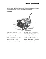
Page 6: ...HP OHV engine Air Cleaner Protects the engine by filtering dust and debris from the intake air Choke Used to start the engine Recoil Starter Used to start the engine Fuel Valve Turn this valve to the...

Page 7: ...00 Watts of power 12 V 8 3 A DC this receptacle allows you to recharge a 12 Volt automotive or utility style storage battery with the battery charge cables provided This receptacle cannot charge 6 Vol...

Page 8: ...2 pieces Vibration Mounts 2 pieces Handle Assembly 1 set Handle Lock Pins 2 pieces Bolt Kit Wheel Retaining Pins 2 pieces Flat Washers 2 pieces Cap Screws and Nuts 10 sets Spark Arrester Kit Spark Arr...

Page 9: ...bend the legs of the cotter pin back around the axle 7 Repeat steps 3 6 to attach the second wheel Install the Support Leg 1 Attach the rubber vibration mount to the support leg with a cap screw M8x20...

Page 10: ...qualified technician to inspect and repair the LPG system CAUTION Use approved LP cylinders equipped with an OPD overfilling prevention device valve Always keep the cylinder in a vertical position wi...

Page 11: ...pull rapidly 7 As engine warms up move the choke lever to Run NOTE If the engine starts but does not run make certain that the generator is on a flat level surface The engine is equipped with a low oi...

Page 12: ...he chart to determine approximate wattage requirements for your equipment NOTE Starting watts can exceed three times the running watts The values in the following table are approximate Refer to your t...

Page 13: ...Add 0 63 qt 0 6 L of oil and replace oil fill cap dipstick 6 Dispose of used oil at an approved waste management facility Spark Plugs CAUTION Allow the engine to cool before removing the spark plug 1...

Page 14: ...lp line at 877 338 0999 to locate the nearest Champion Power Equipment certified service dealer for your generator or engine maintenance needs Every 8 hours or daily Check oil level Clean around air i...

Page 15: ...l valve 4 Close the manual shutoff valve on the LPG cylinder and disconnect from the generator 5 Change the oil 6 Remove the spark plug and pour about ounce of oil into the cylinder Crank the engine s...

Page 16: ...uel Use only an approved LPG cylinder equipped with an OPD valve Flow rate 1 1 kg hr Outlet pressure 2 8 kpa 0 5 kpa Oil Oil capacity is 0 63 qt 0 6 L Spark Plugs Your generator comes equipped with a...

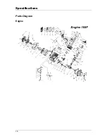
Page 17: ...Specifications 16 Parts Diagram Engine...

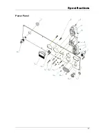
Page 18: ...Specifications 17 Power Panel...

Page 19: ...Specifications 18 Generator...

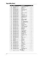
Page 20: ...26 GF2 041105 01 14 01 Fly Wheel 1 27 GF2 041105 01 01 01 Oil Seal 2 28 GB T5789 Bolt M6 25 2 29 GF2 041105 01 15 02 Ignition 1 30 GF2 041105 01 01 6 Dowel Pin 2 31 GF2 041105 01 00 13 Bolt M8 55 4 32...

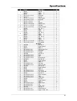
Page 21: ...15 04 Spark Plug 1 80 GF2 041105 01 04 02 Cylinder Head Complete 1 81 GF2 041105 01 01 4 Cylinder Head Gasket 1 82 GF2 041105 01 04 6 Intake Valve 1 83 GF2 041105 01 04 7 Exhaust Valve 1 84 GF2 041105...

Page 22: ...09 02 00 1 Generator End Cover 1 5 GF2 011105 02 00 2 Wire Jacket 1 6 GF2 041209 02 00 01 Terminal 1 7 GB T5789 Bolt M5 20 6 8 GF2 041209 02 00 02 Bridge 1 9 GF2 041209 02 00 03 AVR 1 10 GF2 041209 02...

Page 23: ...2 GF2 041105 50 00 06 Bottom Rubber 1 2 43 GF2 041105 50 00 07 Bottom Rubber 2 2 44 GF2 011105 50 00 05 Rubber Nog 2 45 GT2 041105 50 00 44 Bottom Rubber 2 1 46 GB T41 Nut M6 4 GT2 041105 50 00 027 Ha...

Page 24: ...overloaded Review load and adjust See Power Management Generator cannot supply enough power or overheating Insufficient ventilation Check for air restriction Move to a well ventilated area Cable not...

Page 25: ...s and or labor if this generator is deemed to have been misused neglected involved in an accident abused loaded beyond the generator s limits modified installed improperly or connected incorrectly to...

Page 26: ...subject to provisions set forth below If during the warranty period emission related part on your engine is defective in materials or workmanship the part will be repaired or replaced by CPE OWNER WAR...

Page 27: ...e effect of repair or replace as necessary shall not reduce the ECS Warranty Period Any such part repaired or replaced under the ECS Warranty shall be warranted for the remainder of the ECS Warranty P...

Page 28: ...e listed systems TO OBTAIN WARRANTY SERVICE You must take your CPE engine or the product on which it is installed along with your warranty registration card or other proof of original purchase date at...

Page 29: ...Notes 28 Notes...
Reviews: