background image

16

100250 - 37 TON FULL BEAM LOg SPLiTTER

ASSEMBLY

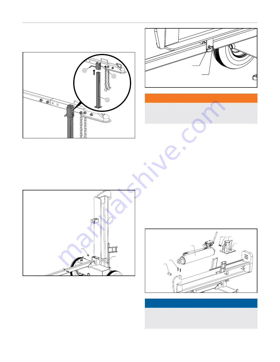
4) install the Support Leg

1.  Insert the support leg (67) into the leg holder on the tow bar 

and secure with pin (66) and R-pin (38).

67

38

66

5) install the Beam

1.  Stand the beam (1) vertical on the foot plate.

2.  Roll the tank into position so the pivot holes of the tank and 

beam are aligned.

3.  Insert the bolt (36) and secure it with the lock nut (34).

1

34

36

4.  Block the wheels to prevent the frame from rolling.

5.  Pivot the beam to the horizontal position and secure it with 

the lock pin (37) and R-clip (38) through the tow bar.

38

37

16

2

4

5

3

17

18


WARNiNg

The beam is extremely heavy and should only be handled 
with 2 or more people. DO NOT try and lift or handle the beam 
without assistance.

6) install the Cylinder and Wedge

1.  Slide the wedge (4) under the beam rails. Push it toward the 

foot plate to make room for the cylinder (16).

2.  Position the cylinder clevis between the mounting plates at 

the end of the beam.

3.  Align the holes in the cylinder clevis to the holes on the 

mounting channels on the beam.

4.  Slide the cylinder pin (18) through the mounting channel and 

cylinder clevis holes and secure with the two R-clips (17).

5.  Align the holes in the cylinder rod end with the holes in the 

wedge.

6.  Secure the cylinder rod end to the wedge with the bolt (5), 

washer (3) and lock nut (2). Tighten, but DO NOT over tighten.

38

37

16

2

4

5

3

17

18


NOTiCE

The cylinder rod may need to be rotated slightly in order to 
properly align the wedge. Insert a screwdriver into the bolt 
hole in the cylinder rod and slowly rotate as needed.

Summary of Contents for 100250

Page 1: ...ains important safety precautions which should be read and understood before operating the product Failure to do so could result in serious injury This manual should remain with the product Specificat...

Page 2: ...owing Log Splitter Safety 20 Log Splitter Location 21 Starting the Engine 21 Stopping the Engine 22 Log Splitter Operation 22 Operation at High Altitude 23 Maintenance 23 Cleaning the Log splitter 23...

Page 3: ...ways exercise common sense and always err on the side of caution when operating the product to ensure no accident property damage or injury occurs We want you to continue to use and be satisfied with...

Page 4: ...hands and feet away from rotating parts Tie up long hair and remove jewelry Operate equipment with guards in place DO NOT wear loose fitting clothing dangling drawstrings or items that could become ca...

Page 5: ...regulations restrictions and registration CAUTION Improper treatment or use of the log splitter can damage it shorten its life and void your warranty Use the log splitter only for intended uses Opera...

Page 6: ...developed in hydraulic log splitters Pressurized hydraulic fluid escaping through a pin hole opening can puncture skin and cause sever blood poisoning Therefore the following instructions should be h...

Page 7: ...hands on the sides of the log not the ends Never place your hands or any part of your body between a log and any part of the log splitter 10 On ram type log splitters never attempt to split more than...

Page 8: ...Exhaust gases muffler and engine components are extremely HOT and cause burns ADVERTENCIA NO TOCAR Los gases de escape el silenciador y los compnonentes del motor est n extremadamente CALIENTES y cau...

Page 9: ...full face shield as well as full ear protection when operating this product Footwear Always wear safety shoes or heavy boots when operating the machine Gloves Always wear nonslip heavy duty protective...

Page 10: ...d any part of the log splitter Do not split logs against the grain Split logs end to end in the direction of the grain only Toxic Fumes The engine exhaust from this product contains chemicals known to...

Page 11: ...P Rev A Size 90 x 40 mm Artwork Notes 3mm corner radius 2mm safe margin Revision Changes This artwork belongs to Champion Power Equipment The contents are confidential and privileged and shall not be...

Page 12: ...hydraulic cylinder in place 3 Hydraulic Cylinder Converts hydraulic pressure into linear force 4 Control Valve Handle Controls the movement of the cutting wedge 5 Wedge 6 Splitting Beam 7 Log Cradle P...

Page 13: ...ke Used to start the engine 5 Recoil Starter Used to manually start the engine 6 Oil Drain Bolt Used to drain the oil from the engine 7 Oil Fill Cap Dipstick Used to check and fill oil level 8 Engine...

Page 14: ...n 1 Use for either Vertical or Horizontal R Pin 1 Cylinder 1 Cylinder Pin 1 R Pin 2 Wedge 1 Bolt M12 75 12 9 1 1 18mm wrench or socket Nut M12 1 1 19mm wrench or socket Flat Washer 12 1 External Hydra...

Page 15: ...l the Wheels 1 Remove the two plastic shipping caps from the wheel hubs 2 Slide the wheel 27 onto the axle Be sure the tire valve stem is facing out 3 Thread the castle nut 25 on the axle and tighten...

Page 16: ...nd lift or handle the beam without assistance 6 Install the Cylinder and Wedge 1 Slide the wedge 4 under the beam rails Push it toward the foot plate to make room for the cylinder 16 2 Position the cy...

Page 17: ...Thread bolt and washers through a hole on the bottom of the engine mount into the engine and add the lock nut Torque to 44 52 ft lbs 4 Repeat steps 1 3 for the rest of the engine mounting hardware 47...

Page 18: ...AX MIN OIL DIP STICK NOTICE Once oil has been added a visual check should show oil about 1 2 threads from running out of the fill hole If using the dipstick to check oil level DO NOT screw in the dips...

Page 19: ...he gasoline to the log splitter DO NOT fill tank indoors DO NOT fill tank when the engine is running or hot DO NOT overfill the tank DO NOT light cigarettes or smoke when filling the tank WARNING Pour...

Page 20: ...efore operating If the engine is equipped with a spark arrestor clean and inspect it regularly follow spark arrestor maintenance schedule 4 The tires need to be fully inflated and in good repair Refer...

Page 21: ...void the warranty NEVER attach a rope cable or other device to the control lever on the log splitter DO NOT modify or change the engine and operating speeds or pressure settings These changes can cau...

Page 22: ...WAYS wear ear and eye protection protective clothing and safety gear 2 Block tires and ensure support leg is secure to prevent unintended movement of the log splitter during operation 3 Set log splitt...

Page 23: ...ons lower than the recommended minimum altitude can damage the engine For operation at lower elevations the originally supplied standard main jet must be used Operating the engine with the wrong engin...

Page 24: ...plug Cleaning the Air Filter 1 Using your fingers unscrew the thumb screws of the top holes of the air filter cover 2 Remove the plastic outer casing 3 Remove the foam element 4 Wash in liquid deterge...

Page 25: ...ours of use Then every 100 hours or seasonally NOTICE Refer to Specifications for a list of compatible replacement filters or call Champion Power Equipment at 1 877 338 0999 to order a replacement OEM...

Page 26: ...Add a properly formulated fuel stabilizer to the tank 2 Run the engine for a few minutes so the treated fuel cycles through the fuel system and carburetor 3 Turn the fuel valve to the OFF position 4...

Page 27: ...ment 338 cc Type 4 Stroke OHV Start Type Recoil Oil Specifications DO NOT OVERFILL Type See chart below Capacity 37 2 fl oz 1 1 L 20 0 20 40 60 Ambient temperature Recommended Engine Oil Type 80 100 1...

Page 28: ...arance 0 007 0 009 in 0 18 0 22 mm NOTICE A technical bulletin regarding valve adjustment procedures is available at www championpowerequipment com Important Message About Temperature Your product is...

Page 29: ...29 100250 37 Ton Full Beam Log Splitter Specifications Parts Diagram TO F F TO A A TO B B C TO C TO D D E TO E...

Page 30: ...Tank 1 31 PMJ22G 19 Oil Plug 1 32 G1160 2 89 Oil Scale 1 33 PMJ22G 18 Screw NPT 1 in 1 34 G889 1 2000 M18 Lock Nut M18 1 35 G5782 2000 M12 85 Bolt M12x85 2 36 PMJ37N 14 Bolt M18x145 1 37 PMJ22J 15 Pin...

Page 31: ...15 13 42 43 44 45 46 134 136 137 133 134 107 138 139 140 141 142 143 144 145 131 132 135 47 48 49 50 51 52 53 54 55 56 13 57 58 59 60 61 62 63 64 65 66 67 68 69 70 71 72 73 74 75 76 77 78 79 80 81 82...

Page 32: ...1 38 46 031000 00 48 Oil Dipstick Assembly Yellow 1 39 45 030007 01 Cover Crankcase 1 40 22 031000 01 48 Oil Filler Cap Yellow 1 41 1 5789 0840 Flange Bolt M8 40 7 Part Number Description Qty 42 2 03...

Page 33: ...k 1 111 1 5789 0832 Flange Bolt M8 32 2 112 46 070011 00 Pipe Fuel Tank To Fuel Valve 1 113 24 070400 00 Fuel Valve 1 114 1 16674 0512 2 Flange Bolt M5 12 1 115 46 070011 01 Pipe Fuel Valve To Carbure...

Page 34: ...l motion is smooth Debris lodged in beam guides Clear debris from beam Low hydraulic oil Check oil level and add as needed Oil leak from hose connection Loose hose clamp or hydraulic fitting Tighten h...

Page 35: ...aintenance This warranty will not apply to parts and or labor if the product is deemed to have been misused neglected involved in an accident abused loaded beyond the product s limits modified install...

Page 36: ...able condition exits CPE will repair your small off road engine SORE at no cost to you including diagnosis parts and labor MANUFACTURER S WARRANTY COVERAGE This exhaust and evaporative emission contro...

Page 37: ...d for the period of time prior to the first scheduled replacement point for that part If the part fails prior to the first scheduled replacement the part shall be repaired or replaced by CPE according...

Page 38: ...Mounting Brackets Carburetor Purge Port Connector TO OBTAIN WARRANTY SERVICE You must take your CPE engine or the product on which it is installed along with your warranty registration card or other p...

Reviews: