10
Electric (Optional) and Recoil Start
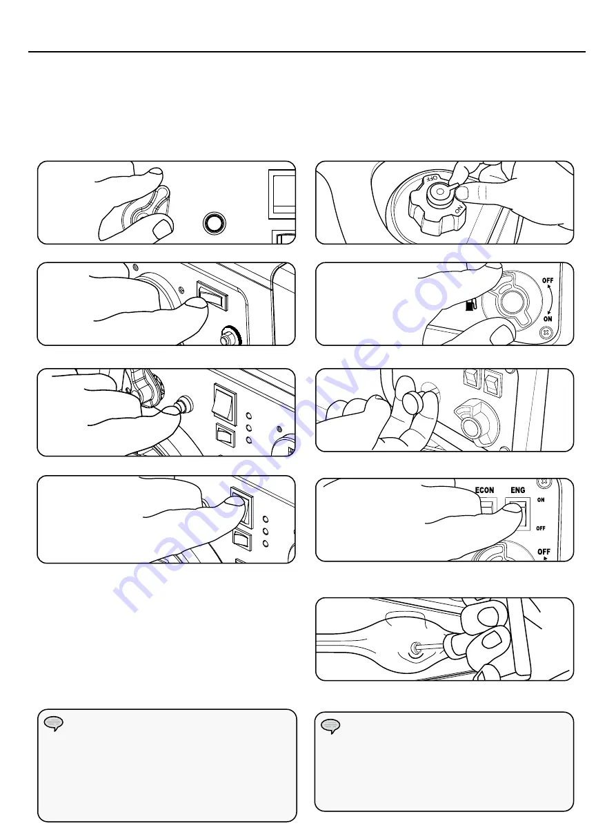
1. Make certain the generator is on a flat, level surface.
2. Disconnect all electrical loads from the generator.
Never start or stop the generator with electrical
devices plugged in or turned on.
3. Turn the fuel valve to the “On” position.
Recoil Start - Alternate Model
1. Make certain the generator is on a flat, level surface.
2. Disconnect all electrical loads from the generator.
Never start or stop the generator with electrical
devices plugged in or turned on.
3. Turn the fuel cap vent lever to the “On”position.
4. Turn the battery switch to the “On” position.
4. Turn the fuel valve to the “On” position.
5. Push the Choke button in to the “Choke” position.
5. Pull the Choke lever out when starting the generator.
6. Turn the ignition switch to the “On” position.
6. Turn the ignition switch to the “On” position.
OPERATION
If the engine starts but does not continue to run
make certain that the generator is on a flat, level
surface. The engine is equipped with a low oil
sensor that will prevent the engine from running
when the oil level falls below a critical threshold.
NOTE
Keep choke button in “Choke” position for only 1
pull of the recoil starter. After first pull, push choke
button to the “Run” position for up to the next 3
pulls of the recoil starter. Too much choke leads to
spark plug fouling/engine flooding due to the lack of
incoming air. This will cause the engine not to start.
NOTE
7. ELECTRIC START: Press and hold the ignition
switch to the “START” position. Release as the
engine begins to roll over. If the engine fails to start
within five seconds, release the switch and wait at
least ten seconds before attempting to start the
engine again.
8. RECOIL START: Pull the starter cord slowly until
resistance is felt and then pull rapidly.
9. As engine warms up, push the choke button to the
“Run” position.
7. Pull the starter cord slowly until resistance is felt
and then pull rapidly.
8. As engine warms up, push the choke button to the
“Run” position.
Summary of Contents for 71001I EU
Page 90: ...90 TECHNICAL DIAGRAMS 71001I EU SC PARTS DIAGRAM ...
Page 92: ...92 TECHNICAL DIAGRAMS 71001I EU SC PARTS DIAGRAM ...
Page 93: ...93 Technical Diagrams 71001I EU SC PARTS LIST 71001i EN ...
Page 96: ...96 TECHNICAL DIAGRAMS 72301i 72301I EU SC PARTS DIAGRAM ...
Page 97: ...97 Technical Diagrams 72301I EU SC PARTS LIST 72301i EN ...
Page 100: ...100 TECHNICAL DIAGRAMS 73001i P EU 73001I P EU SC PARTS DIAGRAM ...
Page 101: ...101 Technical Diagrams 73001I P EU SC PARTS LIST 73001i P EU EN ...
Page 102: ...102 TECHNICAL DIAGRAMS 73001i P EU 73001I P EU SC PARTS DIAGRAM ...
Page 104: ...104 TECHNICAL DIAGRAMS 71001i 71001I EU SC WIRING DIAGRAM ...
Page 107: ...107 Technical Diagrams 73001i P EU 73001I P EU SC WIRING DIAGRAM EN ...
Page 108: ......


