background image

8


ASSEMBLy

Add Fuel (Petrol) Cont’d.

Our engines work well with 10% or less ethanol 
blend fuels. When using blended fuels there are 
some issues worth noting: 


– Ethanol-petrol blends can absorb more water 

than petrol alone. 


– These blends can eventually separate, leaving 

water or a watery goo in the tank, fuel valve and 
carburetor. 


– With gravity-fed fuel supplies, this compromised 

fuel can be drawn into the carburetor and cause 
damage to the engine and/or potential hazards. 


– There are only a few suppliers of fuel stabilizer 

that are formulated to work with ethanol blend 
fuels.


– Any damages or hazards caused by using 

improper fuel, improperly stored fuel, and/
or improperly formulated stabilizers, are not 
covered by manufacture’s warranty. 

It is advisable to always shut off the fuel supply, 
run the engine to fuel starvation and drain the tank 
when the equipment is not in use for more than 30 
days.

NOTE

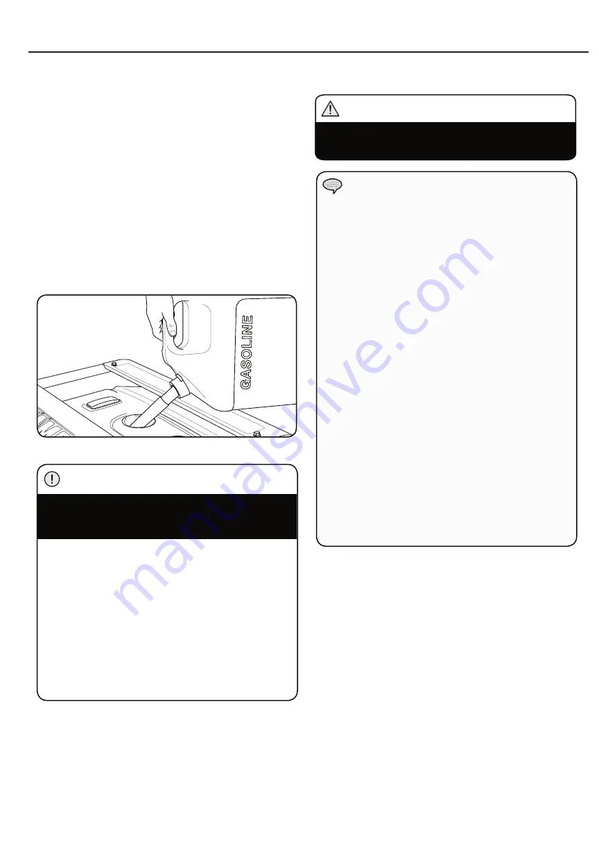
Add Fuel (Petrol)

1.  Use clean, fresh, regular unleaded fuel.
2.  DO NOT mix oil with fuel.
3.  Clean the area around the fuel cap. 
4.  Remove the fuel cap.
5.  Slowly add fuel to the tank. DO NOT OVERFILL. 

Fuel can expand after filling. A minimum of                   
6.4 mm (¼ in.) of space left in the tank is required 
for fuel expansion, more than 6.4 mm (¼ in.) is 
recommended. Fuel can be forced out of the tank as 
a result of expansion if it is overfilled, and can affect 
the stable running condition of the product. When 
filling the tank, it is recommended to leave enough 
space for the fuel to expand.

6.  Screw on the fuel cap and wipe away any spilled fuel.

Use regular unleaded petrol with a minimum octane 
rating of 85.

Do not mix oil and petrol.
Fill tank to approximately 6.4 mm (¼ in.) below the 
top of the tank to allow for fuel expansion.
DO NOT pump petrol directly into the generator at 
the petrol station. Use an approved container to 
transfer the fuel to the generator.
DO NOT fill fuel tank indoors.
DO NOT fill fuel tank when the engine is running or hot.
DO NOT overfill the fuel tank.
DO NOT light cigarettes or smoke when filling the 
fuel tank.

CAUTION

Pouring fuel too fast through the fuel screen may 
result in blow back of fuel at the operator while filling.

WARNING

Summary of Contents for CPG5500E2DF-J

Page 1: ...SAVE THESE INSTRUCTIONS Important Safety Instructions are included in this manual DUAL FUEL GENERATOR CHAMPION GENERATOR 5500W ENGLISH JAPANESE...

Page 2: ......

Page 3: ...see Add Engine Oil section For Fuel Type see Add Fuel section Introduction Congratulations on purchasing your generator Please follow these instructions and maintain it correctly Accessories CPE manu...

Page 4: ...not avoided may result in minor or moderate injury CAUTION CAUTION used without the safety alert symbol indicates a potentially hazardous situation which if not avoided may result in property damage C...

Page 5: ...ged or frayed DO NOT operate generator in wet weather DO NOT allow children or unqualified persons to operate or service the generator Use a ground fault circuit interrupter GFCI in damp areas and are...

Page 6: ...apacity can damage the generator and or electrical devices connected to it DO NOT overload the generator Start the generator and allow the engine to stabilize before connecting electrical loads Connec...

Page 7: ...OSIVE Fire or explosion can cause severe burns or death Unintentional startup can result in entanglement traumatic amputation or laceration DANGER When adding or removing Petrol Turn the generator off...

Page 8: ...ed 1 Before adding fuel and oil tip the generator on it s end 2 Slide the Roll Pin through the Wheel from the outside 3 Slide the Roll Pin through the mount point on the frame 4 Secure with the R clip...

Page 9: ...motive oil NOTE Synthetic oil may be used after the 5 hour initial break in period Using synthetic oil does not increase the recommended oil change interval Full synthetic 5W 30 oil will aid in starti...

Page 10: ...oil with fuel 3 Clean the area around the fuel cap 4 Remove the fuel cap 5 Slowly add fuel to the tank DO NOT OVERFILL Fuel can expand after filling A minimum of 6 4 mm in of space left in the tank is...

Page 11: ...een plugged or kept closed must also be purged The purging process should be done by a LPG supplier Cylinders from an exchange supplier should have been purged and filled properly already Always posit...

Page 12: ...Using a generator or electrical appliance in wet conditions such as rain or snow or near a pool or sprinkler system or when your hands are wet could result in electrocution WARNING WARNING During oper...

Page 13: ...o the ON position 4 Move the choke lever to the 100 CHOKE detent position a For restarting a warm engine move the choke lever to the 75 CHOKE detent position 5 Push the battery switch to the ON positi...

Page 14: ...ot over choke As soon as engine starts gradually move the choke lever to the RUN position over a 2 5 second duration 10 RECOIL START Move the choke lever to the 100 Choke detent position a For restart...

Page 15: ...z loads to the generator DO NOT overload the generator Connecting a generator to your electric utility company s power lines or to another power source may be against the law In addition this action i...

Page 16: ...wing the steps listed under Power Management will guarantee that only one device will be starting at a time Power Management Use the following formula to convert voltage and amperage to watts Volts x...

Page 17: ...ed to firmly install the plug 8 Attach the spark plug wire to the plug Maintenance replacement or repair of emission control devices and systems may be performed by any non road engine repair establis...

Page 18: ...engine performance CAUTION Maintenance And Storage To be performed by knowledgeable experienced owners or Champion Power Equipment certified dealers Generator Maintenance Make certain that the generat...

Page 19: ...he the OFF position and the battery leads have been disconnected from the battery DANGER Generator Battery This product is equipped with an automatic battery charging circuit The battery will receive...

Page 20: ...nder Low oil level Fill crankcase to the proper level Place generator on a flat level surface Generator cannot supply enough power or overheating Generator is overloaded Review load and adjust See Pow...

Page 21: ...19 Champion Generator 5500W JP...

Page 22: ...20...

Page 23: ...21 GFCI 91 4 cm 3 1 5 m 5 JP...

Page 24: ...22...

Page 25: ...23 OFF LPG LPG LPG PG OFF LPG LPG LPG LPG LPG 2 LPG LPG LPG LPG JP...

Page 26: ...24 1 2 3 1 2 3 4 R 5 2 1 2 1 2 3 1 2 1 2 2...

Page 27: ...25 1 2 3 4 Full Synthetic 5W 30 Degrees Celsius Outside Outside Degrees Fahrenheit 10W 30 5 5W 30 5 C 41 F 5 50 5 1 2 JP...

Page 28: ...26 10 30 1 2 3 4 5 6 4mm 6 4mm 6 85 6 4 mm...

Page 29: ...27 OPD LPG 12 AWG 2 052mm 3 309mm2 1 8kg 10kg LP LP LPG 1 2 LPG LPG LPG 3 4 LPG 5 LPG JP...

Page 30: ...28 1 5m 91 4cm 1 CSA UL1449 AC...

Page 31: ...29 ON OFF LPG LPG A B 1 A 2 B 1 2 15 C 59 F 1 2 3 ON 4 100 CHOKE a 75 CHOKE 5 ON 6 ON 7 START 5 10 8 9 2 5 RUN 1 a 60 Hz b 50Hz 2 3 1 RUN 3 JP...

Page 32: ...AH 1 5 Start LPG 1 2 3 LPG 4 LPG ON 5 ON 6 ON 7 75 a 75 CHOKE 8 START 5 10 9 2 5 RUN 10 100 a 100 CHOKE 11 100 1 2 LPG 15 C 75 100 2 10 RUN 100 1 2 30 C 1 75 RUN 3 15 C 100 C H O K E 5 20 RUN 12 RUN 1...

Page 33: ...31 LPG LPG LPG LPG LPG 1 2 100 200 AC 50 Hz 60 Hz 1 2 3 OFF 4 LPG LPG CLOSE OFF 5 6 OFF 7 OFF OFF LPG LPG 2 JP...

Page 34: ...32 1 2 3 1 2 1 1 2 3 4 5 6 7 5 6...

Page 35: ...33 1 2 3 4 5 6 7 1 2 3 4 0 7 0 8 mm 5 6 7 0 7 0 8 mm 0 028 0 031 in 1 15 mm 2 3 4 5 6 1 2 JP...

Page 36: ...34 25 PSI 1 2 3 4 5 6 25PSI 8 5 50 100 250 3 LPG...

Page 37: ...35 14 1 20 1 2 3 4 5 6 7 8 9 14 8mL 1 2 10 11 OFF 2 1 1 2 M5 10 M5 3 1 2 4 1 5 1 JP...

Page 38: ...36 OFF ON LPG AC AVR AVR https www youtube com watch v olRvvKBIyN0...

Page 39: ...Hz 6625W 60 Hz 5800 50 Hz 5300W 60 Hz 4500 50 Hz 27 5A 60 Hz 24A 50 Hz 55A 60 Hz 48A 50 Hz 66 25A 60 Hz 58A 50 Hz 33 13A 60 Hz 29A 50 Hz 53A 60 Hz 45A 50 Hz 69A 60 Hz 62A 50 Hz 34 5A 60 Hz 31A 50 Hz 2...

Page 40: ...ane Starting Amps 200V Propane Running Amps 100V Propane Running Amps 200V Volts 100 200 Frequency 60 Hz 50Hz Outlets 100V 200V American Standard GFCI Outlets No Covered Outlets Yes Gasoline Run Time...

Page 41: ...G Y OFF G Y G Y 3 4 5 2 1 6 G Y G Y SWITCH lb l la EARTH TERMINAL B W W R R R G Y B B W G Y W R G Y W L B W B Y Y Y G Y W G W G W R B B G Y G Y Y W G FUSE 5A GAS LPG SWITCH a c d f b e c e a b f d L W...

Page 42: ...7 58 1 3 5 6 7 11 12 13 50 53 54 51 52 62 63 64 65 66 67 68 69 70 71 76 77 78 79 70 88 89 90 91 92 94 96 97 98 93 99 101 102 103 104 63 105 70 107 110 109 111 125 126 128 129 127 130 135 136 137 4 12...

Page 43: ...eel Black 2 69 122 201501 25 Pin Roll 16 x 10 x 107 2 70 1 6177 1 08 Lock Nut M8 Flange 9 71 152 201200 04 Motor Mount 2 1 72 152 201200 00 Motor Mount 2 73 2 03 040 Washer 8 x 24 x 3 2 74 1 93 08 Loc...

Page 44: ...3 32 30 28 29 31 27 26 12 24 25 100 101 99 97 98 102 103 104 105 106 107 91 110 108 109 92 93 94 95 96 85 86 87 88 12 111 90 91 89 63 64 47 48 45 46 49 50 52 51 55 12 54 53 56 57 58 60 61 59 62 40 41...

Page 45: ...5 2 57 2 15 002 F6RTC Spark Plug F6RTC 1 58 2 08 014 Flange Bolt M10 x 80 4 59 46 020002 00 Gasket Cylinder Head Cover 1 Part Number Description Qty 60 47 021000 00 Cover Cylinder Head 1 61 45 020001...

Page 46: ......

Page 47: ......

Page 48: ...814 0714 6 23 18...

Reviews: